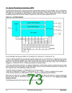
SPCTL (Address=85H, SPI Control Register, Reset Value=0000,0100B)
7
6
5
4
3
2
1
0
SSIG
SPEN DORD MSTR CPOL CPHA
SPR1
SPR0
SSIG: /SS is ignored
If SSIG=1, MSTR decides whether the device is a master or slave.
If SSIG=0, the /SS pin decides whether the device is a master or slave.
SPEN: SPI enable
If SPEN=1, the SPI is enabled.
If SPEN=0, the SPI interface is disabled and all SPI pins will be general-purpose I/O ports.
DORD: SPI data order
1 : The LSB of the data byte is transmitted first.
0 : The MSB of the data byte is transmitted first.
MSTR: Master/Slave mode select
CPOL: SPI clock polarity select
1: SPICLK is high when Idle. The leading edge of SPICLK is the falling edge and the trailing edge is
the rising edge.
0: SPICLK is low when Idle. The leading edge of SPICLK is the rising edge and the trailing edge is
the falling edge.
CPHA: SPI clock phase select
1: Data is driven on the leading edge of SPICLK, and is sampled on the trailing edge.
0: Data is driven when /SS pin is low (SSIG=0) and changes on the trailing edge of SPICLK. Data is
sampled on the leading edge of SPICLK.
(Note : If SSIG=1, CPHA must not be 1, otherwise the operation is not defined.)
SPR1-SPR0: SPI clock rate select (in master mode)
00 : Fosc/4
01 : Fosc/16
10 : Fosc/64
11 : Fosc/128 (Where, Fosc is the system clock.)
SPSTAT (Address=84H, SPI Status Register, Reset Value=00xx,xxxxB)
7
6
5
4
3
2
1
0
SPIF
WCOL
-
-
-
-
-
-
SPIF: SPI transfer completion flag
When a serial transfer finishes, the SPIF bit is set and an interrupt is generated if SPI interrupt is enabled. If /SS
pin is driven low when SPI is in master mode with SSIG=0, SPIF will also be set to signal the “mode change”.
The SPIF is cleared in software by writing ‘1’ to this bit.
WCOL: SPI write collision flag.
The WCOL bit is set if the SPI data register, SPDAT, is written during a data transfer (see Section 15.6: Write
Collision). The WCOL flag is cleared in software by writing ‘1’ to this bit.
SPDAT (Address=86H, SPI Data Register, Reset Value=0000,0000B)
7
6
5
4
3
2
1
0
(MSB)
(LSB)
SPDAT has two physical buffers for writing to and reading from during transmit and receive, respectively.
MEGAWIN
MPC82G516A Data Sheet
74

 MEGAWIN [ MEGAWIN TECHNOLOGY CO., LTD ]