List of Figures
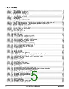
Figure 3-1. Block Diagram ..................................................................................................................................10
Figure 4-1. Pin Assignment: 40-Pin PDIP...........................................................................................................11
Figure 4-2. Pin Assignment: 28-Pin SSOP .........................................................................................................11
Figure 4-3. Pin Assignment: 44-Pin PLCC..........................................................................................................12
Figure 4-4. Pin Assignment: 44-Pin PQFP .........................................................................................................12
Figure 4-5. Pin Assignment: 48-Pin LQFP..........................................................................................................13
Figure 5-1. Program Memory..............................................................................................................................18
Figure 5-2. Data Memory ....................................................................................................................................20
Figure 5-3. Lower 128 Bytes of Internal RAM.....................................................................................................20
Figure 5-4. SFR Space .......................................................................................................................................21
Figure 5-5. External RAM Accessing by an 8-Bit Address (using ‘MOVX @ Ri’ and Page Bits) .......................22
Figure 5-6. External RAM Accessing by a 16-Bit Address (using ‘MOVX @ DPTR’) ........................................22
Figure 8-1. “MOVX @DPTR,A” without Stretch.................................................................................................33
Figure 8-2. “MOVX @DPTR,A” with Stretch......................................................................................................33
Figure 8-3. “MOVX A,@DPTR” without Stretch.................................................................................................34
Figure 8-4. “MOVX A,@DPTR” with Stretch......................................................................................................34
Figure 9-1. Use of Dual DPTR............................................................................................................................35
Figure 10-1. Quasi-Bidirectional I/O....................................................................................................................37
Figure 10-2. Open-Drain Output .........................................................................................................................38
Figure 10-3. Input-Only .......................................................................................................................................38
Figure 10-4. Push-Pull Output ............................................................................................................................38
Figure 11-1. Timer 1 in Mode 0: 13-Bit Timer/Counter.......................................................................................41
Figure 11-2. Timer 1 in Mode 1: 16-Bit Timer/Counter.......................................................................................42
Figure 11-3. Timer 1 in Mode 2: 8-Bit Auto-Reload............................................................................................42
Figure 11-4. Timer 0 in Mode 3: Two 8-Bit Timer/Counters ...............................................................................43
Figure 11-5. Programmable Clock-Out from Timer 0 .........................................................................................44
Figure 11-6. Timer 2 in Capture Mode................................................................................................................46
Figure 11-7. Timer 2 in Auto-Reload Mode (DCEN=0).......................................................................................47
Figure 11-8. Timer 2 in Auto-Reload Mode (DCEN=1).......................................................................................47
Figure 11-9. Timer 2 in Baud Rate Generator Mode ..........................................................................................48
Figure 11-10. Programmable Clock-Out from Timer 2 .......................................................................................50
Figure 12-1. Serial Port Mode 0..........................................................................................................................57
Figure 12-2. Serial Port Mode 1..........................................................................................................................58
Figure 12-3. Serial Port Mode 2..........................................................................................................................59
Figure 12-4. Serial Port Mode 3..........................................................................................................................60
Figure 12-5. UART Framing Error Detection ......................................................................................................61
Figure 12-6. UART Multiprocessor Communication, Auto Address Recognition ...............................................62
Figure 13-1. New Baud Rate Source for the 1st UART.......................................................................................65
Figure 13-2. Programmable Clock-Out from UART2 Baud Rate Timer .............................................................66
Figure 14-1. PCA Block Diagram........................................................................................................................67
Figure 14-2. PCA Timer/Counter ........................................................................................................................68
Figure 14-3. PCA Interrupt System.....................................................................................................................69
Figure 14-4. PCA Capture Mode ........................................................................................................................70
Figure 14-5. PCA Software Timer Mode.............................................................................................................71
Figure 14-6. PCA High Speed Output Mode.......................................................................................................71
Figure 14-7. PCA PWM Mode.............................................................................................................................72
Figure 15-1. SPI Block Diagram .........................................................................................................................73
Figure 15-2. SPI single master single slave configuration..................................................................................75
Figure 15-3. SPI dual device configuration, where either can be a master or a slave .......................................75
Figure 15-4. SPI single master multiple slaves configuration.............................................................................76
Figure 15-5. SPI Slave Transfer Format with CPHA=0 ......................................................................................79
Figure 15-6. Slave Transfer Format with CPHA=1 .............................................................................................79
Figure 15-7. SPI Master Transfer Format with CPHA=0 ....................................................................................80
Figure 15-8. SPI Master Transfer Format with CPHA=1 ....................................................................................80
Figure 16-1. ADC Block Diagram........................................................................................................................81
Figure 18-1. WDT Block Diagram.......................................................................................................................86
Figure 19-1. Interrupt System .............................................................................................................................90
Figure 20-1. Flash Configuration ........................................................................................................................96
Figure 20-2. Flow Chart for “Flash Page Erase”.................................................................................................99
Figure 20-3. Flow Chart for “Flash Program”....................................................................................................100
5
MPC82G516A Data Sheet
MEGAWIN
 MEGAWIN [ MEGAWIN TECHNOLOGY CO., LTD ]
