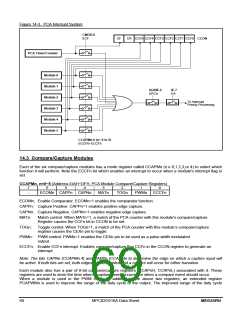
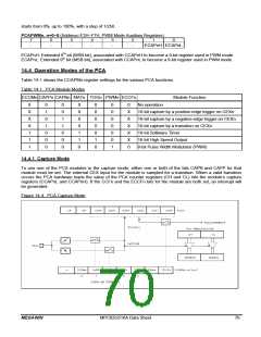
Figure 14-3. PCA Interrupt System
CMOD.0
ECF
CF
CR CCF5 CCF4 CCF3 CCF2 CCF1 CCF0
CCON
PCA Timer/Counter
Module 0
Module 1
Module 2
Module 3
Module 4
Module 5
AUXIE.2
EPCA
IE.7
EA
To Interrupt
Priority Processing
CCAPMn.0 (n= 0 to 5)
ECCF0~ECCF5
14.3 Compare/Capture Modules
Each of the six compare/capture modules has a mode register called CCAPMn (n e 0,1,2,3,or 4) to select which
function it will perform. Note the ECCFn bit which enables an interrupt to occur when a module's interrupt flag is
set.
CCAPMn, n=0~5 (Address=DAH~DFH, PCA Module Compare/Capture Registers)
7
6
5
4
3
2
1
0
-
ECOMn CAPPn CAPNn
MATn
TOGn
PWMn
ECCFn
ECOMn: Enable Comparator. ECOMn=1 enables the comparator function.
CAPPn: Capture Positive. CAPPn=1 enables positive edge capture.
CAPNn: Capture Negative. CAPNn=1 enables negative edge capture.
MATn:
Match control. When MATn=1, a match of the PCA counter with this module’s compare/capture
Register causes the CCFn bit in CCON to be set.
TOGn:
Toggle control. When TOGn=1, a match of the PCA counter with this module’s compare/capture
register causes the CEXn pin to toggle.
PWMn: PWM control. PWMn=1 enables the CEXn pin to be used as a pulse width modulated
output.
ECCFn: Enable CCFn interrupt. Enables compare/capture flag CCFn in the CCON register to generate an
interrupt.
Note: The bits CAPNn (CCAPMn.4) and CAPPn (CCAPMn.5) determine the edge on which a capture input will
be active. If both bits are set, both edges will be enabled and a capture will occur for either transition.
Each module also has a pair of 8-bit compare/capture registers (CCAPnH, CCAPnL) associated with it. These
registers are used to store the time when a capture event occurred or when a compare event should occur.
When a module is used in the PWM mode, in addition to the above two registers, an extended register
PCAPWMn is used to improve the range of the duty cycle of the output. The improved range of the duty cycle
69
MPC82G516A Data Sheet
MEGAWIN

 MEGAWIN [ MEGAWIN TECHNOLOGY CO., LTD ]