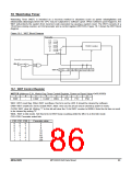
18 Watchdog Timer
Watchdog Timer (WDT) is intended as a recovery method in situations (such as power noise/glitches and
electrostatic discharge) where the CPU may be subjected to software upset. When software upset happens, the
WDT will protects the system from incorrect code execution by causing a system reset. The WDT consists of a
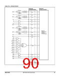
15-bit free-running counter, an 8-bit prescaler and a control register (WDTCR). Figure 18-1 shows the WDT block
diagram.
Figure 18-1. WDT Block Diagram
18.1 WDT Control Register
WDTCR (Address=E1H, Watch-Dog-Timer Control Register, Power-on Reset Value=0x00,0000B)
7
6
5
4
3
2
1
0
WRF
-
ENW
CLRW
WIDL
PS2
PS1
PS0
WRF: WDT reset flag. When WDT overflows, this bit is set by H/W. It should be cleared by software.
ENW: WDT enable bit. Set to enable WDT. (Note: Once set, this bit can only be cleared by power-on reset.)
CLRW: WDT clear bit. Writing “1” to this bit will clear the 15-bit WDT counter to 0000H. Note this bit has no need
to be cleared by writing “0”.
WIDL: WDT in Idle mode. Set this bit to let WDT keep counting while the MCU is in the Idle mode.
PS2~PS0: Prescaler select bits.
PS2 PS1 PS0
Prescaler value
0
0
0
0
1
1
1
1
0
0
1
1
0
0
1
1
0
1
0
1
0
1
0
1
2
4
8
16
32
64
128
256
MEGAWIN
MPC82G516A Data Sheet
86

 MEGAWIN [ MEGAWIN TECHNOLOGY CO., LTD ]