1°C Accurate Remote/Local Temperature
Sensor with SMBus Serial Interface
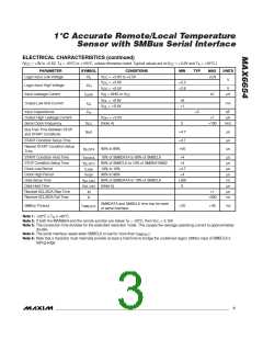
ELECTRICAL CHARACTERISTICS (continued)
(V
= +3V to +5.5V, T = -551C to +1251C, unless otherwise noted. Typical values are at V
= +3.3V and T = +251C.)
CC A
CC
A
PARAMETER
SYMBOL
CONDITIONS
= +3.0V to +5.5V
MIN
TYP
MAX
UNITS
Logic Input Low Voltage
Logic Input High Voltage
Input Leakage Current
V
V
V
V
V
V
V
+0.8
IL
CC
CC
CC
V
= +3.0V
= +5.5V
+2.2
+2.6
V
IH
V
I
= GND or V
= +0.6V
2
µA
LEAK
IN
CC
+6
+1
OL
OL
Output Low Sink Current
I
mA
OL
= +0.4V
Input Capacitance
C
+5
pF
µA
in
Output High Leakage Current
Serial Clock Frequency
V
= +5.5V
+1
OH
f
(Note 4)
0
+100
kHz
SCL
Bus Free Time Between STOP
and START Conditions
t
+4.7
+4.7
+50
µs
µs
µs
BUF
START Condition Setup Time
Repeat START Condition Setup
Time
t
90% to 90%
SU:STA
START Condition Hold Time
STOP Condition Setup Time
Clock Low Period
t
t
10% of SMBDATA to 90% of SMBCLK
90% of SMBCLK to 10% of SMBDATA662
10% to 10%
+4
+4
µs
µs
µs
µs
ns
µs
µs
ns
HD:STA
SU:STO
t
+4.7
+4
LOW
Clock High Period
t
90% to 90%
HIGH
Data Setup Time
t
90% of SMBDATA to 10% of SMBCLK
(Note 5)
+250
0
SU: DAT
t
HD: DAT
Data Hold Time
Receive SCL/SDA Rise Time
Receive SCL/SDA Fall Time
t
+1
R
t
F
+300
SMBDATA and SMBCLK time low for reset
of serial interface
SMBus Timeout
t
+25
+40
ms
TIMEOUT
Note 1: +25°C ≤ T ≤ +85°C.
A
Note 2: If both the MAX6654 and the remote junction are below T = -20°C, then V
> 3.15V.
A
CC
Note 3: The conversion time doubles for the extended resolution mode. This causes the average operating current to approximately
double.
Note 4: The serial interface resets when SMBCLK is low for more than t
.
TIMEOUT
Note 5: Note that a transition must internally provide at least a hold time to bridge the undefined region (300ns max) of SMBCLK’s
falling edge.
_______________________________________________________________________________________
3

 MAXIM [ MAXIM INTEGRATED PRODUCTS ]