+5V-Powered, Multichannel RS-232
Drivers/Receivers
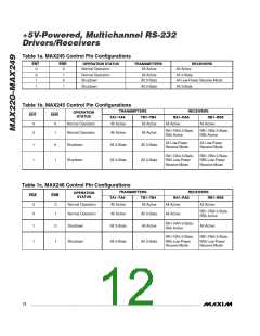
Table 1a. MAX245 Control Pin Configurations
OPERATION STATUS
Normal Operation
Normal Operation
Shutdown
TRANSMITTERS
All Active
RECEIVERS
ENT
ENR
0
0
±
±
0
±
0
±
All Active
All 3-State
All Active
All 3-State
All Low-Power Receive Mode
All 3-State
Shutdown
All 3-State
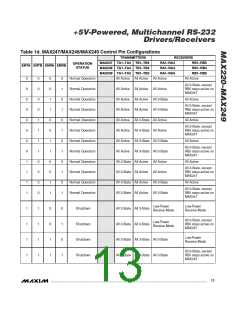
Table 1b. MAX245 Control Pin Configurations
TRANSMITTERS
RECEIVERS
OPERATION
STATUS
ENT
ENR
TA1–TA4
TB1–TB4
RA1–RA5
All Active
RB1–RB5
All Active
0
0
0
±
Normal Operation
Normal Operation
All Active
All Active
RA±–RA4 3-State,
RA5 Active
RB±–RB4 3-State,
RB5 Active
All Active
All 3-State
All Active
All 3-State
All Low-Power
Receive Mode
All Low-Power
Receive Mode
±
±
0
±
Shutdown
Shutdown
RA±–RA4 3-State,
RA5 Low-Power
Receive Mode
RB±–RB4 3-State,
RB5 Low-Power
Receive Mode
All 3-State
All 3-State
Table 1c. MAX246 Control Pin Configurations
TRANSMITTERS
RECEIVERS
OPERATION
STATUS
ENA
ENB
TA1–TA4
TB1–TB4
RA1–RA5
All Active
RB1–RB5
0
0
0
±
Normal Operation
Normal Operation
All Active
All Active
All Active
RB±–RB4 3-State,
RB5 Active
All Active
All 3-State
All 3-State
All Active
All Active
RA±–RA4 3-State,
RA5 Active
±
±
0
±
Shutdown
Shutdown
All Active
RA±–RA4 3-State,
RA5 Low-Power
Receive Mode
RB±–RB4 3-State,
RA5 Low-Power
Receive Mode
All 3-State
All 3-State
12 ______________________________________________________________________________________

 MAXIM [ MAXIM INTEGRATED PRODUCTS ]