MAX1 6 1 7 Te m p e ra t u re S e n s o r
Eva lu a t io n Kit
If an interrupt condition is generated, typically by the
Da t a Lo g g in g
Data logging commands are accessed via the pull-down
menu labeled “MAX1617”. Data logging saves temperature
data for both channels to a text file that includes a time/date
stamp next to each data point. At high conversion rates, not
every data point is logged, depending on the speed of the
disk drive where the file is being written. To stop data log-
ging, select Logging from the pull-down menu.
7
temperature crossing one of the alarm threshold levels,
a message appears in the alert box: “ALERT! INT =
LOW”. To clear the interrupt, first eliminate the condi-
tion that caused it (typically by resetting the alarm
threshold) and then click on Read Alert. This action
reads the Alert Response address, returns the value of
the current MAX1617 slave address, and clears the
interrupt.
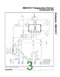
J u m p e r a n d S w it c h S e t t in g s
Two jump e rs s e t the MAX1617 s la ve a d d re s s . The
default address is 0101 010 (ADD0 = ADD1 = high-Z);
to get other settings, jumper JU1 and/or JU2 must be
installed (Figure 1). JU1 responds to ADD0 and JU2
corresponds to ADD1; see Table 8 in the MAX1617
data sheet for a complete list of slave addresses. The
MAX1617 must undergo a power-on reset for the new
address to become effective.
S im p le S MBu s Co m m a n d s
There are two methods for communicating with the
MAX1617: via the normal user-interface panel, or via
the s imp le SMBus c omma nd s a va ila b le from the
SMBus pull-down menu. The menu lists simple SMBus
protocols, such as Read Byte and Write Byte. To stop
normal user-interface execution so that it does not over-
ride the manually set values, turn off the update timer
that slaves the program to the conversion rate by click-
ing the Automatically Update Displays button.
A slide switch, SW1, is provided as a means to force a
power-on reset of the MAX1617. This switch simply dis-
ables power to the device.
Evluates:MAX61
Note that in places where the slave address asks for an
8-bit value, it must be the 7-bit slave address of the
MAX1617 as determined by ADD0 and ADD1 with the
last LSB bit always set to one.
The STBY hardware standby control input is hard-wired to
V
CC
. In order to apply an external disabling signal to STBY,
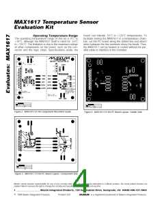
the narrow PC board trace at JU3 must first be cut. Figure 2
is a component placement guide. Figures 3 and 4 are the PC
board layout.
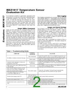
Table 1. Troubleshooting Guide
POSSIBLE
SYMPTOM
PROBLEM
SOLUTION
Check the parallel cable. If it is a straight-through type, try a
different cable or connect directly to the port with no cable.
Bad connections
No SMBus Hardware Detected message
Power supply
Check the supply voltage setting for correct polarity. Use a
DMM to check the voltage directly at the board.
Check the connections to the device. The SMBus interface is
working, but the MAX1617 is not. Check the position of the
slide switch.
Question marks displayed in status and
temperature data fields
No MAX1617
connected
SMB Clock Stuck Low or SMB Data Stuck
Low message
Use a DMM to monitor the SMBCLK and SMBDATA terminals.
They may be accidentally shorted.
Short circuit
Both channels always read 0°C, or new
limits are not accepted, or ALERT inter-
rupts are not seen by the program.
Check the +9V supply. The board may be parasitically
deriving power from the parallel-port logic signals.
Bad power supply
The supply voltage at V is too low
CC
(<4.5V) but is higher than 1V.
DXP and DXN are
shorted together, or
DXP is shorted to GND
Remote diode always reads 0°C.
Remote diode always reads +127°C.
Check remote diode connections.
DXP open
Check remote diode connections.
Excess resistance
Excess capacitance
Poor-quality diode
Check resistance in diode path.
Remote diode reads a value that is too
high.
Check capacitance from DXP to DXN.
Use a good-quality, diode-connected, small-signal transistor.
2
_______________________________________________________________________________________

 MAXIM [ MAXIM INTEGRATED PRODUCTS ]