DS2781
FUNCTION COMMANDS
After successfully completing one of the net address commands, the bus master can access the features of the
DS2781 with any of the function commands described in the following paragraphs. The name of each function is
followed by the 8-bit opcode for that command in square brackets. The function commands are summarized in
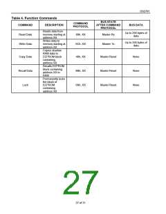
Table 4.
Read Data [69h, XX]. This command reads data from the DS2781 starting at memory address XX. The LSb of the
data in address XX is available to be read immediately after the MSb of the address has been entered. Because
the address is automatically incremented after the MSb of each byte is received, the LSb of the data at address XX
+ 1 is available to be read immediately after the MSb of the data at address XX. If the bus master continues to read
beyond address FFh, data is read starting at memory address 00 and the address is automatically incremented
until a reset pulse occurs. Addresses labeled “Reserved” in the memory map contain undefined data values. The
Read Data command can be terminated by the bus master with a reset pulse at any bit boundary. Reads from
EEPROM block addresses return the data in the shadow RAM. A Recall Data command is required to transfer data
from the EEPROM to the shadow. See the Memory section for more details.
Write Data [6Ch, XX]. This command writes data to the DS2781 starting at memory address XX. The LSb of the
data to be stored at address XX can be written immediately after the MSb of address has been entered. Because
the address is automatically incremented after the MSb of each byte is written, the LSb to be stored at address XX
+ 1 can be written immediately after the MSb to be stored at address XX. If the bus master continues to write
beyond address FFh, the data starting at address 00 is overwritten. Writes to read-only addresses, reserved
addresses and locked EEPROM blocks are ignored. Incomplete bytes are not written. Writes to unlocked EEPROM
block addresses modify the shadow RAM. A Copy Data command is required to transfer data from the shadow to
the EEPROM. See the Memory section for more details.
Copy Data [48h, XX]. This command copies the contents of the EEPROM shadow RAM to EEPROM cells for the
EEPROM block containing address XX. Copy data commands that address locked blocks are ignored. While the
copy data command is executing, the EEC bit in the EEPROM register is set to 1 and writes to EEPROM
addresses are ignored. Reads and writes to non-EEPROM addresses can still occur while the copy is in progress.
The copy data command takes tEEC time to execute, starting on the next falling edge after the address is
transmitted.
Recall Data [B8h, XX]. This command recalls the contents of the EEPROM cells to the EEPROM shadow memory
for the EEPROM block containing address XX.
Lock [6Ah, XX]. This command locks (write-protects) the block of EEPROM memory containing memory address
XX. The LOCK bit in the EEPROM register must be set to 1 before the lock command is executed. To help prevent
unintentional locks, one must issue the lock command immediately after setting the LOCK bit (EEPROM register,
address 1Fh, bit 06) to a 1. If the LOCK bit is 0 or if setting the lock bit to 1 does not immediately precede the lock
command, the lock command has no effect. The lock command is permanent; a locked block can never be written
again.
26 of 31

 MAXIM [ MAXIM INTEGRATED PRODUCTS ]