DS2781
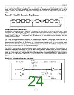
In the circuit in Figure 23, the shift register bits are initialized to 0. Then, starting with the least significant bit of the
family code, one bit at a time is shifted in. After the 8th bit of the family code has been entered, then the serial
number is entered. After the 48th bit of the serial number has been entered, the shift register contains the CRC
value.
Figure 23. 1-Wire CRC Generation Block Diagram
INPUT
MSb
LSb
XOR
XOR
XOR
HARDWARE CONFIGURATION
Because the 1-Wire bus has only a single line, it is important that each device on the bus be able to drive it at the
appropriate time. To facilitate this, each device attached to the 1-Wire bus must connect to the bus with open-drain
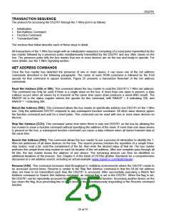
or tri-state output drivers. The DS2781 uses an open-drain output driver as part of the bidirectional interface
circuitry shown in Figure 24. If a bidirectional pin is not available on the bus master, separate output and input pins
can be connected together.
The 1-Wire bus must have a pullup resistor at the bus-master end of the bus. For short line lengths, the value of
this resistor should be approximately 5kΩ. The idle state for the 1-Wire bus is high. If, for any reason, a bus
transaction must be suspended, the bus must be left in the idle state to properly resume the transaction later. If the
bus is left low for more than 120μs (16μs for overdrive speed), slave devices on the bus begin to interpret the low
period as a reset pulse, effectively terminating the transaction.
The DS2781 can operate in two communication speed modes, standard and overdrive. The speed mode is
determined by the input logic level of the OVD pin with a logic 0 selecting standard speed and a logic 1 selecting
overdrive speed. The OVD pin must be at a stable logic level of 0 or 1 before initializing a transaction with a reset
pulse. All 1-Wire devices on a multinode bus must operate at the same communication speed for proper operation.
1-Wire timing for both standard and overdrive speeds are listed in the Electrical Characteristics: 1-Wire Interface
tables.
Figure 24. 1-Wire Bus Interface Circuitry
Vpullup
(2.0V to 5.5V)
BUS MASTER
DS2781 1-WIRE PORT
4.7kΩ
Rx
RX
TX
0.2μA
(typ)
Tx
RX = RECEIVE
TX = TRANSMIT
100Ω
MOSFET
24 of 31

 MAXIM [ MAXIM INTEGRATED PRODUCTS ]