DS2781
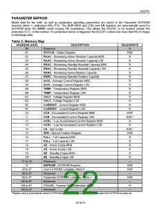
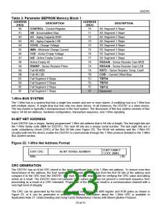
Table 3. Parameter EEPROM Memory Block 1
ADDRESS
DESCRIPTION
(HEX)
ADDRESS
(HEX)
DESCRIPTION
AE Segment 4 Slope
60
61
62
63
64
65
66
67
68
69
6A
6B
6C
6D
6E
6F
CONTROL - Control Register
AB - Accumulation Bias
AC - Aging Capacity MSB
AC - Aging Capacity LSB
VCHG - Charge Voltage
IMIN - Minimum Charge Current
VAE - Active Empty Voltage
IAE - Active Empty Current
Active Empty 40
70
71
72
73
74
75
76
77
78
79
7A
7B
7C
7D
7E
7F
AE Segment 3 Slope
AE Segment 2 Slope
AE Segment 1 Slope
SE Segment 4 Slope
SE Segment 3 Slope
SE Segment 2 Slope
SE Segment 1 Slope
RSGAIN - Sense Resistor Gain MSB
RSNSP - Sense Resistor Prime
Full 40 MSB
RSGAIN - Sense Resistor Gain LSB
RSTC - Sense Resistor Temp. Coeff.
Full 40 LSB
COB – Current Offset Bias
Full Segment 4 Slope
Full Segment 3 Slope
Full Segment 2 Slope
Full Segment 1 Slope
TBP34
TBP23
TBP12
Reserved
1-Wire BUS SYSTEM
The 1-Wire bus is a system that has a single bus master and one or more slaves. A multidrop bus is a 1-Wire bus
with multiple slaves. A single-drop bus has only one slave device. In all instances, the DS2781 is a slave device.
The bus master is typically a microprocessor in the host system. The discussion of this bus system consists of four
topics: 64-bit net address, hardware configuration, transaction sequence, and 1-Wire signaling.
64-BIT NET ADDRESS
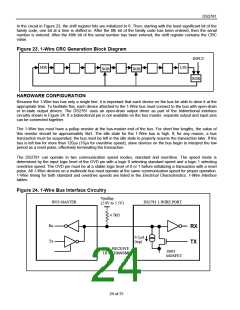
Each DS2781 has a unique, factory-programmed 1-Wire net address that is 64 bits in length. The first eight bits are
the 1-Wire family code (3Dh for DS2781). The next 48 bits are a unique serial number. The last eight bits are a
cyclic redundancy check (CRC) of the first 56 bits (see Figure 22). The 64-bit net address and the 1-Wire I/O
circuitry built into the device enable the DS2781 to communicate through the 1-Wire protocol detailed in the 1-Wire
Bus System section.
Figure 22. 1-Wire Net Address Format
8-BIT FAMILY
CODE (3Dh)
8-BIT CRC
MSb
48-BIT SERIAL NUMBER
LSb
CRC GENERATION
The DS2781 has an 8-bit CRC stored in the most significant byte of its 1-Wire net address. To ensure error-free
transmission of the address, the host system can compute a CRC value from the first 56 bits of the address and
compare it to the CRC from the DS2781. The host system is responsible for verifying the CRC value and taking
action as a result. The DS2781 does not compare CRC values and does not prevent a command sequence from
proceeding as a result of a CRC mismatch. Proper use of the CRC can result in a communication channel with a
very high level of integrity.
The CRC can be generated by the host using a circuit consisting of a shift register and XOR gates as shown in
Figure 23, or it can be generated in software. Additional information about the 1-Wire CRC is available in
Application Note 27: Understanding and Using Cyclic Redundancy Checks with Maxim iButton Products.
23 of 31

 MAXIM [ MAXIM INTEGRATED PRODUCTS ]