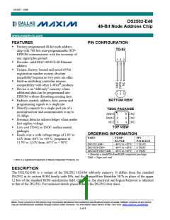
DS2502-E48
The first 32 bytes of the DS2502-E48’s EPROM memory contain a globally unique 48-bit node address
and are write-protected. The data structure follows the conventions of UniqueWare devices using Default
Data Structure (Figure 1). This format is also known as UDP (universal data packet) and is commonly
used in 1-Wire APIs. Therefore, if using one of those APIs one can call a high level function to read and
verify the inverted CRC16. The UDP is defined in Application Note 114, 1-Wire File Structure, and the
APIs can be found in the 1-Wire Software Development Kits.
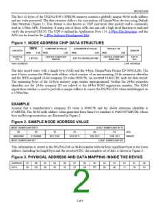
Figure 1. NODE ADDRESS CHIP DATA STRUCTURE
COMPANY ID VALUE
EXTENSION ID VALUE
PROJECT ID
CRC16
MSB LSB
(UNUSED)
LENGTH
MSB LSB
MSB LSB MSB
LSB
19 BYTES
FFh
3 BYTES CONSTANT
006035h
4 BYTES CONSTANT
00001129h
1 BYTE
0Ah
2 BYTES
3 BYTES SERIALIZATION
HIGH ADDRESS
LOW ADDRESS
The data record starts with a length byte (0Ah) and the 4-byte UniqueWare Project ID 00001129h. The
next 6 bytes contain the 48-bit node address which consists of an incrementing 24-bit extension identifier
and the IEEE-assigned 24-bit company ID value 006035h. An inverted 16-bit CRC ends the data record.
The remaining bytes of the 32-byte memory page remain unprogrammed. Neither the 24-bit extension
identifier nor the 24-bit company ID are related to the 64-bit ROM registration number. The ROM
registration number is used to provide a unique address to access the DS2502-E48 when multidropped on
a 1-Wire bus.
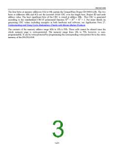
EXAMPLE
Assume that a manufacturer’s company ID value is 006035h and the 24-bit extension identifier is
67ABCDh. The 48-bit node address value generated from these two numbers is 00603567ABCDh, whose
byte and bit representations are illustrated in Figure 2.
Figure 2. SAMPLE NODE ADDRESS VALUE
MOST SIGNIFICANT BYTE
LEAST SIGNIFICANT BYTE
CD
00
60
35
67
AB
1010 1011
LEAST SIGNIFICANT BIT
HEX
0000 0000
0110 0000
0011 0101
0110 0111
1100 1101
BINARY
MOST SIGNIFICANT BIT
This information is stored in the DS2502-E48 as 48-bit number with the least significant byte at the lower
address. Including the length byte and the inverted CRC, the complete set of data is shown in Figure 3.
Figure 3. PHYSICAL ADDRESS AND DATA MAPPING INSIDE THE DEVICE
ADDRESS
DATA
0C
8D
0B
0A
00
09
60
08
35
07
67
06
05
04
00
03
00
02
11
01
29
00
0A
DD
AB
CD
2 of 4

 MAXIM [ MAXIM INTEGRATED PRODUCTS ]