108-98001 Rev. M
AXICOM Signal Relays
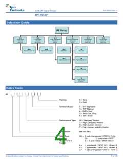
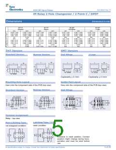
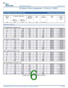
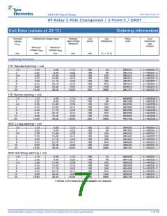
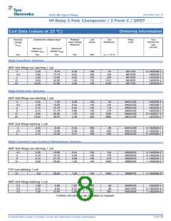
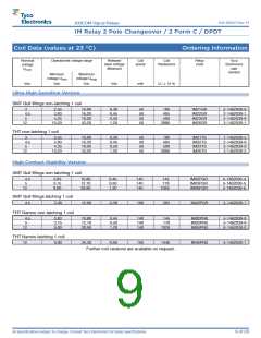
IM Relay 2 Pole Changeover / 2 Form C / DPDT
Dimensions
Dimensions in mm
IM THT
Standard
IM THT
Narrow
IM SMT
Gull Wings
IM SMT
J-Legs
mm
inch
mm
inch
mm
inch
mm
inch
L
W
H
10.00 ± 0.08
6.00 ± 0.08
5.65 – 0.20
3.2
0.393 ± 0.003
0.236 ± 0.003
0.222 – 0.008
0.125
10.00 ± 0.08
5.70 ± 0.30
5.80 ± 0.08
3.2
0.393 ± 0.003
0.224 ± 0.012
0.230 ± 0.003
0.125
10.00 ± 0.08
6.00 ± 0.08
5.65 – 0.20
N/A
0.393 ± 0.003
0.236 ± 0.003
0.222 – 0.008
N/A
10.00 ± 0.08
6.00 ± 0.08
5.65 – 0.02
N/A
0.393 ± 0.003
0.236 ± 0.003
0.222 – 0.008
N/A
T
T1
T2
D1
D2
Tw
S
N/A
N/A
N/A
N/A
7.50 ± 0.30
5.08 ± 0.10
3.20 ± 0.15
2.20 ± 0.15
0.4
0.295 ± 0.011
0.200 ± 0.004
0.126 ± 0.006
0.087 ± 0.006
0.015
2.80 ± 0.20
5.08 ± 0.10
3.20 ± 0.15
2.20 ± 0.15
0.4
0.110 ± 0.007
0.200 ± 0.004
0.126 ± 0.006
0.087 ± 0.006
0.015
5.08 ± 0.10
3.20 ± 0.15
2.20 ± 0.15
0.40
0.200 ± 0.004
0.126 ± 0.006
0.087 ± 0.006
0.015
3.20 ± 0.10
3.20 ± 0.15
2.20 ± 0.15
0.4
0.126 ± 0.004
0.126 ± 0.006
0.087 ± 0.006
0.015
0.75
0.029
0.30 ± 0.05
0.011 ± 0.002
N/A
N/A
N/A
N/A
THT Version
SMT Version
Standard Version
Narrow Version
Gull Wings
J-Legs
Coplanarity ≤ 0.1mm
Coplanarity ≤ 0.1mm
Mounting Hole Layout
Solder Pad Layout
View onto the component side of the PCB (top view)
View onto the component side of the PCB (top view)
Narrow Version
Gull Wings
Standard Version
Ø min. 0.75
Ø min. 0.75
Terminal Assignment
Relay – top view
Latching Type, 1 Coil
Non-Latching Type
reset condition
not energized condition
Contacts in reset position. Contact
position might change during trans-
portation and must be reset before
use.
All specifications subject to change. Consult Tyco Electronics for latest specifications.
5 of 28

 TE [ TE CONNECTIVITY ]