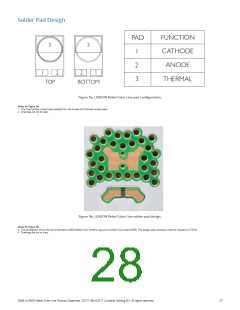
Solder Pad Design
FUNCTION
CATHODE
ANODE
PAD
3
3
1
2
3
1
2
2
1
THERMAL
TOP
BOTTOM
Figure 9a. LUXEON Rebel Color Line pad configuration.
Notes for Figure 9a:
1. The Thermal Pad is electrically isolated from the Anode and Cathode contact pads.
2. Drawings are not to scale.
Figure 9bꢀ LUXEON Rebel Color Line solder pad designꢀ
Notes for Figure 9b:
3. The photograph shows the recommended LUXEON Rebel Color Portfolio layout on printed circuit board (PCB). This design easily achieves a thermal resistance of 7K/W.
4. Drawings are not to scale.
DS68 LUXEON Rebel Color Line Product Datasheet 20171106 ©2017 Lumileds Holding B.V. All rights reserved.
27

 LUMILEDS [ LUMILEDS LIGHTING COMPANY ]