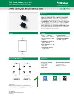
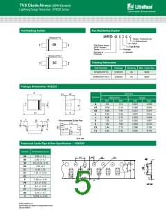
TVS Diode Arrays (SPA® Diodes)
Lightning Surge Protection- SP4020 Series
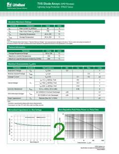
Absolute Maximum Ratings
Symbol
Parameter
Value
30
Units
IPP
Peaꢀ Current (tp=8/20μs)
Peaꢀ Pulse Power (tp=8/20μs)
OperatingTemperature
StorageTemperature
A
750
PPꢀ
W
°C
°C
TOP
-40 to 125
-55 to 150
TSTOR
Notes:
CAUTION: Stresses above those listed in “Absolute Maximum Ratings” may cause permanent damage to the device. This is a stress only rating and operation of
the device at these or any other conditions above those indicated in the operational sections of this specification is not implied.
Thermal Information
Parameter
Rating
-55 to 150
150
Units
°C
StorageTemperature Range
Maximum JunctionTemperature
Maximum LeadTemperature (Soldering 20-40s)
°C
260
°C
Electrical Characteristics (TOP=25ºC)
Parameter
Symbol
Test Conditions
Min
Typ
Max
Units
Breaꢀdown koltage
kBD
IR=2uA
3.5
k
Reverse Standoff koltage
Leaꢀage Current
kRWM
ILEAK
IR≤1μA
3.3
0.5
k
μA
k
kR=3.3k
0.1
6.6
IPP=1A, tp=8/20µs, Fwd
IPP=10A, tp=8/20µs, Fwd
IPP=24A, tP=8/20μs, Fwd
TLP, tP =100ns, I/O to GND
Clamp koltage1
kC
14.2
21.8
0.40
k
k
Dynamic Resistance2
RDYN
kESD
CD
Ω
IEC 61000-4-2 (Contact Discharge)
IEC 61000-4-2 (Air Discharge)
Reverse Bias=0k, f=1MHz
30
30
ꢀk
ꢀk
pF
ESD Withstand koltage1
Diode Capacitance1
2.5
Note:
1Parameter is guaranteed by design and/or device characterization.
2Transmission Line Pulse (TLP) with 100ns width and 200ps rise time.
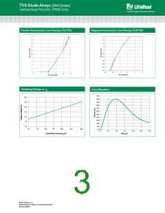
Non-Repetitive Peak Pulse Power vs. PulseTime
Normalized Capacitance vs. BiasVoltage
10
1.4
SP4020-01FTG-C
SP4020-01FTG
1.2
1.0
0.8
0.6
0.4
0.2
0.0
1
0.1
0.01
0.0
0.3
0.6
0.9
1.2
1.5
1.8
2.1
2.4
2.7
3.0
3.3
0.1
1
10
100
1000
Bias Voltage (V)
Pulse Duration - tp (µs)
© 2017 Littelfuse, Inc.
Specifications are subject to change without notice.
Revised: 05/04/17

 LITTELFUSE [ LITTELFUSE ]