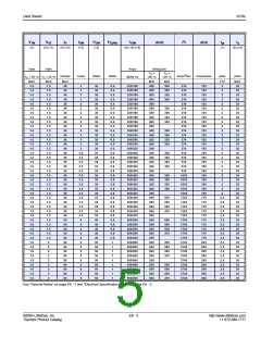
Data Sheets
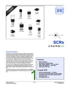
SCRs
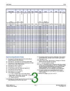
I2t
di/dt
IDRM & IRRM
VTM
(3)
VGT
IH
(5) (13)
IGM
(12)
PGM
(12)
PG(AV)
ITSM
(6) (10)
tgt
(7)
tq
(9) (10)
dv/dt
(14)
(8)
(17)
mAmps
Volts
Volts
Amps
Volts/µSec
T
=
T =
T
=
T
=
T
=
T
=
T =
C
C
C
C
C
C
C
2
60/50 Hz 100 °C 125 °C
25 °C 100 °C 125 °C
MAX
25 °C
MAX
1.6
1.6
1.6
1.6
1.6
1.6
1.6
1.6
1.6
1.6
1.6
1.6
1.6
1.6
1.6
1.6
1.6
1.6
1.6
1.6
1.6
1.6
1.6
25 °C
MAX
1.5
1.5
1.5
1.5
1.5
1.5
1.5
1.5
1.5
1.5
1.5
1.5
1.5
1.5
1.5
1.5
1.5
1.5
1.5
1.5
1.5
1.5
1.5
mAmps
MAX
30
30
30
30
30
30
30
30
30
30
30
30
30
30
30
30
30
30
40
40
40
40
40
Amps
Watts
Watts
Amps Sec Amps/µSec
µSec
TYP
2
2
2
2
2
2
2
2
2
2
2
2
2
2
2
2
2
2
2
2
2
2
2
µSec
MAX
35
35
35
35
35
35
35
35
35
35
35
35
35
35
35
35
35
35
35
35
35
35
35
MIN
40
40
MIN
20
20
0.01
0.01
0.01
0.01
0.01
0.01
0.01
0.02
0.01
0.01
0.01
0.01
0.02
0.01
0.01
0.01
0.02
0.02
0.01
0.01
0.01
0.02
0.02
0.2
0.2
0.2
0.2
0.2
0.2
0.2
3
0.2
0.2
0.2
0.2
3
0.2
0.2
0.2
0.5
3
0.5
0.5
0.5
0.5
3
0.5
0.5
0.5
0.5
0.5
0.5
0.5
1.5
1.5
1.5
2
2
2
2
2
2
2
2
2
2
2
2
2
2
2
15
15
15
20
20
20
20
20
20
20
20
20
20
20
20
20
20
20
20
20
20
20
20
0.3
0.3
0.3
0.5
0.5
0.5
0.5
0.5
0.5
0.5
0.5
0.5
0.5
0.5
0.5
0.5
0.5
0.5
0.5
0.5
0.5
0.5
0.5
30/25
30/25
30/25
3.7
3.7
3.7
41
41
41
41
41
41
41
41
41
41
41
41
41
41
41
60
60
60
60
60
50
50
50
40
20
100/83
100/83
100/83
100/83
100/83
100/83
100/83
100/83
100/83
100/83
100/83
100/83
100/83
100/83
100/83
120/100
120/100
120/100
120/100
120/100
350
350
300
250
100
350
350
300
250
100
350
350
300
250
100
350
350
300
250
100
250
250
225
200
100
100
100
100
100
100
100
100
100
100
100
100
100
100
100
100
100
100
100
100
0.5
0.5
0.5
0.5
250
250
225
200
0.5
0.5
0.5
1
250
250
225
200
1
1
1
1
2
2
2
2
250
250
225
200
2
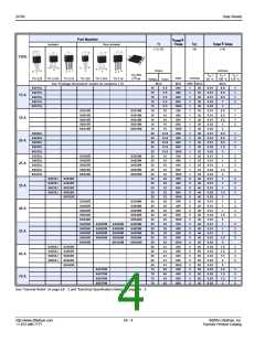
(11) See package outlines for lead form configuration. When ordering
special lead forming, add type number as suffix to part number.
(12) Pulse width ≤10 µs
Electrical Specification Notes
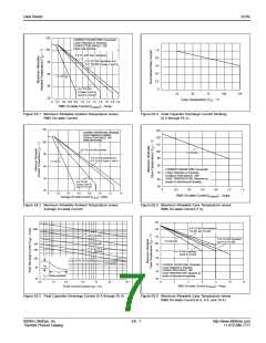
(1) See Figure E6.5 through Figure E6.16 for current rating at
specified operating case temperature.
(2) See Figure E6.1 and Figure E6.2 for free air current rating.
(13) Initial on-state current = 200 mA dc for 1 A through 16 A devices;
400 mA dc for 20 A through 70 A devices.
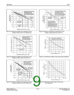
(3) See Figure E6.19 and Figure E6.20 for instantaneous on-state
(14) TC = TJ for test conditions in off state.
current versus on-state voltage (typical).
(15) The R, K, or M package rating is intended for high surge condition
use only and not recommended for ≥50 A rms continuous current
use since narrow pin lead temperature can exceed PCB solder
melting temperature. Teccor's J package or W package is
(4) See Figure E6.18 for IGT versus TC.
(5) See Figure E6.17 for IH versus TC.
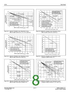
(6) For more than one full cycle rating, see Figure E6.23.
recommended for ≥50 A rms continuous current requirements.
(7) See Figure E6.22 for tgt versus IGT
.
(16) For various durations of an exponentially decaying current
waveform, see Figure E6.3 and Figure E6.4. (tW is defined as
5 time constants.)
(8) See Figure E6.21 for VGT versus TC.
(9) Test conditions are as follows:
(17) Minimum non-trigger VGT at 125 °C is 0.2 V.
• IT = 1 A for 1 A devices and 2 A for all other devices
• Pulse duration = 50 µs, dv/dt = 20 V/µs, di/dt = -10 A/µs for 1 A
devices, and -30 A/µs for other devices
• IGT = 200 mA at turn-on
(10) See Figure E6.5 through Figure E6.10 for maximum allowable
case temperatures at maximum rated current.
©2004 Littelfuse, Inc.
Thyristor Product Catalog
E6 - 3
http://www.littelfuse.com
+1 972-580-7777

 LITTELFUSE [ LITTELFUSE ]