Absolute Maximum Ratings
(Ta=25
Unit
)
Parameter
Symbol
Rating
Forward Current
IF
VR
50
mA
V
Input
Reverse Voltage
6
Power Dissipation
P
70
mW
V
Collector-Emitter Voltage
Emitter-Collector Voltage
Collector Current
VCEO
VECO
IC
35
6
50
V
Output
mA
mW
mW
Collector Power Dissipation
PC
150
Ptot
Topr
Tstg
Viso
Tsol
200
Total Power Dissipation
Operating Temperature
Storage Temperature
*1.Isolation Voltage
-30~+100
-55~+125
5
KVrms
*2.Soldering Temperature
260
*1. AC for 1 minute, R.H. = 40 ~ 60%
Isolation voltage shall be measured using the following method.
(1)Short between anode and cathode on the primary side and between collector, emitter and base on the secondary side.
(2)The isolation voltage tester with zero-cross circuit shall be used.
(3)The waveform of applied volttage shall be a sine wave.
*2. For 10 seconds.
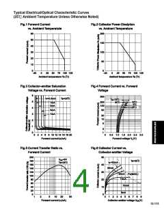
Electrical/Optical Characteristics
(Ta=25
Conditions
)
Parameter
Symbol
Min.
Typ.
Max.
Unit
Forward Voltage
1.2
1.4
10
V
A
IF=20mA
VF
IR
Reverse Current
VR=4V
Terminal Capacitance
Collector Dark Current
30
250
100
pF
nA
V=0, f=1KHz
VCE=20V
Ct
ICEO
Collector-Emitter
Breakdown Voltage
Emitter-Collector
Breakdown Voltage
35
6
V
V
BVCEO
BVECO
IC=0.1mA
IE=10
A
600
30
%
*Current Transfer Ratio
Collector Current
CTR
IC
50
I
F
=5mA, VCE=5V RBE
=
2.5
mA
Collector-emitter
Saturation Voltage
Isolation Resistance
VCE(sat)
0.1
0.2
IF=20mA, IC=1mA
V
1011
0.6
DC500V, 40~60% R.H.
5
1010
RISO
Cf
pF
1.0
Floating Capacitance
V=0, f=1MHz
VCE=5V, IC=2mA
RL=100 , -3dB
KHz
fc
80
Cut-off Frequency
s
s
18
18
Response Time (Rise)
Response Time (Fall)
IC
tr
tf
4
3
VCE=2V, IC=2mA
RL=100
*CTR=
100%
IF
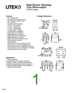
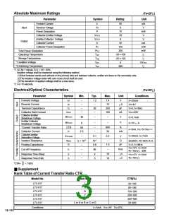
Supplement
Rank Table of Current Transfer Ratio CTR
Model No.
Rank Mark
CTR(%)
LTV-817
LTV-817
LTV-817
LTV-817
LTV-817
LTV-817
L
A
B
C
D
50~100
80~160
130~260
200~400
300~600
50~600
L or A or B or C or D
Conditions
IF=5mA VCE=5V Ta=25
12-112

 LITEON [ LITE-ON TECHNOLOGY CORPORATION ]