LTC2630
ELECTRICAL CHARACTERISTICS The
●
denotes the specifications which apply over the full operating
temperature range, otherwise specifications are at T = 25°C. V = 2.7V to 5.5V, V unloaded unless otherwise specified.
A
CC
OUT
LTC2630-LM12/-LM10/-LM8/-LZ12/-LZ10/-LZ8, LTC2630A-LM12/-LZ12 (V = 2.5V)
FS
SYMBOL PARAMETER
AC Performance
CONDITIONS
MIN
TYP
MAX
UNITS
t
Settling Time
V
= 3V (Note 7)
CC
S
μs
μs
μs
0.39% ( 1LSB at 8 Bits)
0.098% ( 1LSB at 10 Bits)
0.024% ( 1LSB at 12 Bits)
3.2
3.9
4.4
Voltage Output Slew Rate
Capacitive Load Driving
Glitch Impulse
1.0
500
2
V/μs
pF
At Midscale Transition
nV•s
e
Output Voltage Noise Density
At f = 1kHz, Supply as Reference
At f = 10kHz, Supply as Reference
At f = 1kHz, Internal Reference
At f = 10kHz, Internal Reference
140
130
160
150
nV/√Hz
nV/√Hz
nV/√Hz
nV/√Hz
n
Output Voltage Noise
0.1Hz to 10Hz, Supply as Reference
0.1Hz to 10Hz, Internal Reference
0.1Hz to 200kHz, Supply as Reference
0.1Hz to 200kHz, Internal Reference
20
20
650
700
μV
P-P
μV
P-P
μV
P-P
μV
P-P
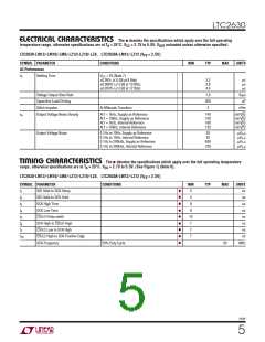
TIMING CHARACTERISTICS The
●
denotes the specifications which apply over the full operating temperature
range, otherwise specifications are at T = 25°C. V = 2.7V to 5.5V. (See Figure 1) (Note 6).
A
CC
LTC2630-LM12/-LM10/-LM8/-LZ12/-LZ10/-LZ8, LTC2630A-LM12/-LZ12 (V = 2.5V)
FS
SYMBOL PARAMETER
CONDITIONS
MIN
4
TYP
MAX
UNITS
ns
●
●
●
●
●
●
●
●
●
t
t
t
t
t
t
t
t
SDI Valid to SCK Setup
SDI Valid to SCK Hold
SCK High Time
1
4
ns
2
9
ns
3
SCK Low Time
9
ns
4
CS/LD Pulse width
10
7
ns
5
SCK High to CS/LD High
CS/LD Low to SCK High
CS/LD High to SCK Positive Edge
SCK Frequency
ns
6
7
ns
7
7
ns
10
50% Duty Cycle
50
MHz
2630f
5

 Linear [ Linear ]