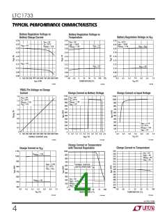
LTC1733
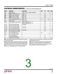
ELECTRICAL CHARACTERISTICS
TA = 25°C. VCC = 5V unless otherwise noted.
SYMBOL
PARAMETER
CONDITIONS MIN
TYP
1.5
MAX
UNITS
V
V
PROG Pin Voltage
R
= 3k, I
= 1V
= 500µA; Current Mode
PROG
PROG
CHRG
PROG
CHRG
CHRG
I
CHRG Pin Weak Pulldown Current
CHRG Pin Output Low Voltage
ACPR Pin Output Low Voltage
FAULT Pin Output Low Voltage
End of Charge Indication Current Level
TIMER Accuracy
V
25
µA
V
V
V
V
I
I
I
= 5mA
0.35
0.35
0.35
50
CHRG
ACPR
FAULT
C/10
= 5mA
= 5mA
V
ACPR
V
FAULT
I
t
R
PROG
= 3k
35
65
mA
%
C
= 0.1µF
±10
TIMER
TIMER
V
Recharge Battery Voltage Threshold
Battery Voltage Falling, SEL = 0V
Battery Voltage Falling, SEL = 5V
3.9
4.0
V
V
RECHRG
V
V
V
V
V
V
V
V
NTC Pin Hot Threshold Voltage
NTC Pin Hot Hysteresis Voltage
NTC Pin Cold Threshold Voltage
NTC Pin Cold Hystersis Voltage
NTC Pin Disable Threshold Voltage
NTC Pin Disable Hystersis Voltage
SEL Pin Threshold Input Low
SEL Pin Threshold Input High
V
V
V
Falling
Rising
Rising
2.5
70
V
mV
V
NTC-HOT
HOT-HYS
NTC-COLD
COLD-HYS
NTC-DIS
DIS-HYS
SEL-IL
NTC
NTC
NTC
4.375
70
mV
mV
mV
V
100
10
0.3
1
V
SEL-IH
T
Junction Temperature in
Constant-Temperature Mode
105
375
°C
LIM
R
Power MOSFET “ON” Resistance
mΩ
ON
Note 1: Absolute Maximum Ratings are those values beyond which the life
of a device may be impaired.
temperature range are assured by design, characterization and correlation
with statistical process controls.
Note 2: The Absolute Maximum BAT Current Rating of 1.6A is guaranteed
by design and current density calculations. The Absolute Maximum PROG
Current Rating is guaranteed to be 1/1000 of BAT current rating by design.
Note 4: Failure to solder the exposed backside of the package to the PC
board will result in a thermal resistance much higher than 40°C/W.
Note 5: Supply current includes PROG pin current but does not include
Note 3: The LTC1733E is guaranteed to meet performance specifications
from 0°C to 70°C. Specifications over the –40°C to 85°C operating
any current delivered to the battery through the BAT pin.
sn1733 1733fs
3

 Linear [ Linear ]