LT3580
PACKAGE DESCRIPTION
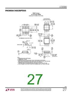
MS8E Package
8-Lead Plastic MSOP
(Reference LTC DWG # 05-08-1662)
BOTTOM VIEW OF
EXPOSED PAD OPTION
2.06 ± 0.102
(.081 ± .004)
1
1.83 ± 0.102
(.072 ± .004)
0.889 ± 0.127
(.035 ± .005)
2.794 ± 0.102
(.110 ± .004)
5.23
(.206)
MIN
3.20 – 3.45
(.126 – .136)
2.083 ± 0.102
(.082 ± .004)
8
3.00 ± 0.102
(.118 ± .004)
(NOTE 3)
0.52
(.0205)
REF
0.65
(.0256)
BSC
0.42 ± 0.038
(.0165 ± .0015)
TYP
8
7 6 5
RECOMMENDED SOLDER PAD LAYOUT
3.00 ± 0.102
(.118 ± .004)
(NOTE 4)
4.90 ± 0.152
(.193 ± .006)
DETAIL “A”
0.254
(.010)
0° – 6° TYP
GAUGE PLANE
1
2
3
4
0.53 ± 0.152
(.021 ± .006)
1.10
(.043)
MAX
0.86
(.034)
REF
DETAIL “A”
0.18
(.007)
SEATING
PLANE
0.22 – 0.38
(.009 – .015)
TYP
0.1016 ± 0.0508
(.004 ± .002)
0.65
(.0256)
BSC
MSOP (MS8E) 0307 REV D
NOTE:
1. DIMENSIONS IN MILLIMETER/(INCH)
2. DRAWING NOT TO SCALE
3. DIMENSION DOES NOT INCLUDE MOLD FLASH, PROTRUSIONS OR GATE BURRS.
MOLD FLASH, PROTRUSIONS OR GATE BURRS SHALL NOT EXCEED 0.152mm (.006") PER SIDE
4. DIMENSION DOES NOT INCLUDE INTERLEAD FLASH OR PROTRUSIONS.
INTERLEAD FLASH OR PROTRUSIONS SHALL NOT EXCEED 0.152mm (.006") PER SIDE
5. LEAD COPLANARITY (BOTTOM OF LEADS AFTER FORMING) SHALL BE 0.102mm (.004") MAX
3580fc
Information furnished by Linear Technology Corporation is believed to be accurate and reliable.
However,noresponsibilityisassumedforitsuse.LinearTechnologyCorporationmakesnorepresenta-
t ion t h a t t he in ter c onne c t ion o f i t s cir cui t s a s de s cr ib e d her ein w ill no t in fr inge on ex is t ing p a ten t r igh t s.
27

 Linear [ Linear ]