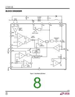
LT3518
APPLICATIONS INFORMATION
UseonlyceramiccapacitorswithX7R,X5Rorbetterdielec-
tric as they are best for temperature and DC bias stability
of the capacitor value. All ceramic capacitors exhibit loss
of capacitance value with increasing DC voltage bias, so
it may be necessary to choose a higher value capacitor
to get the required capacitance at the operation voltage.
Always check that the voltage rating of the capacitor is
sufficient. Table 2 shows some recommended capacitor
vendors.
Table 3. Schottky Diodes
PART NUMBER
On Semiconductor
MBRS260T3
V (V)
I
(A)
R
AVE
60
40
40
60
2
Diodes Inc.
DFLS140L
1
Zetex
ZLLS2000TA
2.2
1.5
International Rectifier
10MQ060N
Table 2. Ceramic Capacitor Manufacturers
VENDOR
Taiyo Yuden
AVX
PHONE
WEB
Board Layout
(408) 573-4150
(843) 448-9411
(770) 436-1300
(847) 803-6100
www.t-yuden.com
www.avxcorp.com
www.murata.com
www.tdk.com
The high speed operation of the LT3518 demands careful
attention to board layout and component placement. The
Exposed Pad of the package is the only GND terminal of
the IC and is also important for thermal management of
the IC. It is crucial to achieve a good electrical and thermal
contact between the Exposed Pad and the ground plane of
the board. To reduce electromagnetic interference (EMI),
it is important to minimize the area of the SW node. Use
a GND plane under SW and minimize the length of traces
in the high frequency switching path between SW and
GND through the diode and the capacitors. Since there is
a small DC input bias current to the ISN and ISP inputs,
resistanceinserieswiththeseinputsshouldbeminimized
and matched, otherwise there will be an offset. Finally, the
Murata
TDK
Loop Compensation
The LT3518 uses an internal transconductance error
amplifier whose V output compensates the control loop.
C
The external inductor, output capacitor, and the compen-
sation resistor and capacitor determine the loop stability.
The inductor and output capacitor are chosen based on
performance, size and cost. The compensation resistor
and capacitor at V are selected to optimize control loop
C
stability.FortypicalLEDapplications,a10nFcompensation
capacitor at V is adequate, and a series resistor is not
C
bypass capacitor on the V supply to the LT3518 should
IN
required.Acompensationresistormaybeusedtoincrease
be placed as close as possible to the V terminal of the
IN
the slew rate on the V pin to maintain tighter regulation
C
device.
of LED current during fast transients on V or CTRL.
IN
Soft-Start
Diode Selection
For many applications, it is necessary to minimize the
inrush current at start-up. The built-in soft-start circuit
significantly reduces the start-up current spike and
outputvoltageovershoot.Atypicalvalueforthesoft-start
capacitor is 0.1μF.
The Schottky diode conducts current during the interval
when the switch is turned off. Select a diode rated for
the maximum SW voltage. If using the PWM feature for
dimming, it is important to consider diode leakage, which
increaseswiththetemperature,fromtheoutputduringthe
PWM low interval. Therefore, choose the Schottky diode
with sufficiently low leakage current. Table 3 has some
recommended component vendors.
3518fb
12

 Linear [ Linear ]