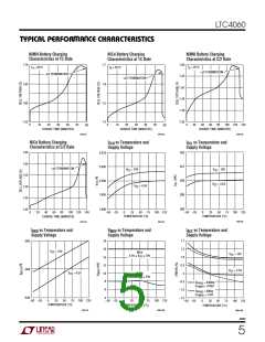
LTC4060
U
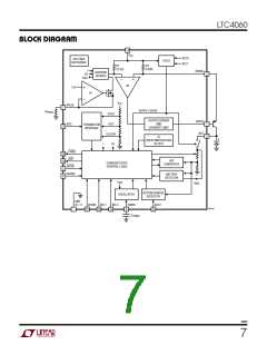
OPERATIO
The charge current is set with an external current pro-
gramming resistor connected between the PROG pin and
GND.IntheBlockDiagram,amplifierA1willcauseavirtual
1.5V to appear on the PROG pin and thus, all of the pro-
grammingresistor’scurrentwillflowthroughtheN-channel
FET to the current divider. The current divider is controlled
by the charger state control logic to produce a voltage
acrossR1, appropriateeitherforprecharge(I/5)orforfast
charge (I), depending on the cell voltage. The current di-
vider also produces a constant current IOSC, that along
with an external capacitor tied to the TIMER pin, sets the
Oscillator’sclockfrequency. Duringcharging, theexternal
PNP transistor’s collector will provide the battery charge
current. The PNP’s emitter current flows into the SENSE
pin and through the internal current sense resistor R2
(0.03Ω). This current is slightly more than the collector
currentsinceitincludesthebasecurrent. AmplifierA2and
the output driver will drive the base of the external PNP
through the DRIVE pin to force the same reference voltage
that appears across R1 to appear across the R2. The pre-
cision ratio between R1 and R2, along with the current
programming resistor, accurately determines the charge
current.
The SHDN pin can be used to return the charger to a
shutdown and reset state. The PAUSE pin can be used to
pause the charge current and internal clocks for any
interval desired.
Fault conditions, such as overheating of the IC due to
excessive PNP base current drive, are monitored and
limited by the IC overtemperature detection and output
driver and current limit blocks.
When either VCC is removed or manual shutdown is
entered, the charger will draw only tiny leakage currents
from the battery, thus maximizing standby time. With VCC
removed, the external PNP’s base is connected to the
battery by the charger. In manual shutdown, the base is
connected to VCC by the charger.
Undervoltage Lockout
An internal undervoltage lockout circuit (UVLO) monitors
the input voltage and keeps the charger in the inactive
sleep mode until VCC rises above the undervoltage exit
threshold. The ACP pin is high impedance while in the
sleep mode and becomes low impedance to ground when
in the active mode. The threshold is dependent upon the
number of series cells selected by the SEL0 and SEL1 pins
(see VUVI1-3 and VUVD1-3 in the Electrical Characteristics
table).TheUVLOcircuithasabuilt-inhysteresisof100mV.
The thresholds are chosen to provide a minimum voltage
drop of approximately 600mV between minimum VCC and
BAT at a battery cell voltage of 1.8V. This helps to protect
against excessive saturation in the external power PNP
when the supply voltage is near its minimum. While
inactive the LTC4060 reduces battery current to just a
negligible leakage current (IBSL).
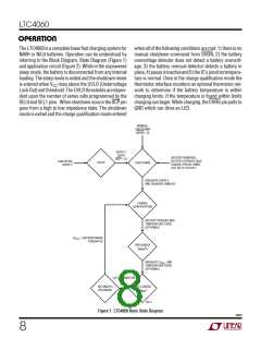
When charging begins, the charger state control logic will
enable precharge of the battery. When the cell voltage
exceedsthefastchargequalificationthreshold,fastcharge
begins. If the cell voltage exceeds the initial delay hold off
threshold voltage just prior to precharge, then the A/D
converter immediately monitors for a –∆V event to
terminate charging while in fast charge. Otherwise, the
fast charge voltage stabilization hold off period must
expire before the A/D converter monitors for a –∆V event
from which to terminate charging. The –∆V magnitude for
termination is selected for either NiMH or NiCd by the
CHEMpin.Shouldthebatterytemperaturebecometoohot
or too cold, charging will be suspended by the charger
state control logic until the temperature enters normal
limits. A termination timer puts the charger into shutdown
mode if the programmed time has expired. After charging
has ended, the optional autorecharge detector function
monitors for the battery voltage to drop to either a default
or externally programmed cell voltage before automati-
cally restarting a charge cycle.
Manual Shutdown Control
The LTC4060 can be forced into a low quiescent current
shutdown while VCC is present by applying a low level to
the SHDN pin. In manual shutdown, charging is inhibited,
the internal timer is reset and oscillator disabled, CHRG
status output is high impedance and ACP continues to
providethecorrectstatus. TheLTC4060willdrawlowcur-
rent from the supply (ISD), and only a negligible leakage
current is applied to the battery (IBSD). If a high level is
4060f
9

 Linear Systems [ Linear Systems ]