Data Sheet
EHW015A0A Series Eighth-Brick Power Modules
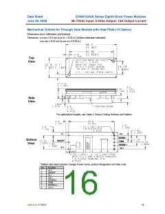
36–75Vdc Input; 5.0Vdc Output; 15A Output Current
June 29, 2009
Surface Mount Information (continued)
Through-Hole Lead-Free Soldering
Information
broken, the floor life of the product at conditions of ≤
30°C and 60% relative humidity varies according to the
MSL rating (see J-STD-033A). The shelf life for dry
packed SMT packages will be a minimum of 12 months
from the bag seal date, when stored at the following
conditions: < 40° C, < 90% relative humidity.
The RoHS-compliant through-hole products use the
SAC (Sn/Ag/Cu) Pb-free solder and RoHS-compliant
components. They are designed to be processed
through single or dual wave soldering machines. The
pins have an RoHS-compliant finish that is compatible
with both Pb and Pb-free wave soldering processes. A
maximum preheat rate of 3°C/s is suggested. The
wave preheat process should be such that the
temperature of the power module board is kept below
210°C. For Pb solder, the recommended pot
temperature is 260°C, while the Pb-free solder pot is
270°C max. Not all RoHS-compliant through-hole
products can be processed with paste-through-hole Pb
or Pb-free reflow process. If additional information is
needed, please consult with your Lineage Power
representative for more details.
Post Solder Cleaning and Drying
Considerations
Post solder cleaning is usually the final circuit-board
assembly process prior to electrical board testing. The
result of inadequate cleaning and drying can affect both
the reliability of a power module and the testability of
the finished circuit-board assembly. For guidance on
appropriate soldering, cleaning and drying procedures,
refer to Lineage Power Board
Mounted Power Modules: Soldering and Cleaning
Application Note (AN04-001).
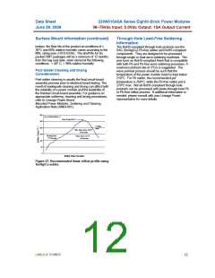
300
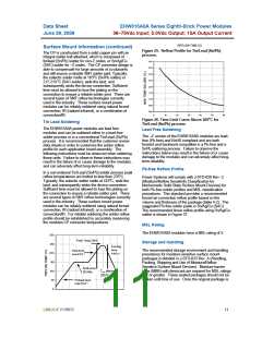
Per J-STD-020 Rev. C
Peak Temp 260°C
250
Cooling
200
Zone
* Min. Time Above 235°C
15 Seconds
150
Heating Zone
1°C/Second
*Time Above 217°C
60 Seconds
100
50
0
Reflow Time (Seconds)
Figure 27. Recommended linear reflow profile using
Sn/Ag/Cu solder.
LINEAGE POWER
12

 LINEAGEPOWER [ LINEAGE POWER CORPORATION ]