King Billion Electronics Co., Ltd
HE84770
駿 億 電 子 股 份 有 限 公 司
HE80000 SERIES
LIO17=0
LIO17=1
PRT170
PRT171
PRT172
PRT173
PRT174
PRT175
PRT176
PRT177
PRT170
PRT171
PRT172
PRT173
PRT174
PRT175
PRT176
PRT177
SEG0
SEG1
SEG2
SEG3
SEG4
SEG5
SEG6
SEG7
LIO15=0
LIO15=1
PRT150
PRT151
PRT152
PRT153
PRT154
PRT155
PRT156
PRT157
PRT150
PRT151
PRT152
PRT153
PRT154
PRT155
PRT156
PRT157
SEG8
SEG9
SEG10
SEG11
SEG12
SEG13
SEG14
SEG15
LIO14=0
LIO14=1
PRT140
PRT141
PRT142
PRT143
PRT144
PRT145
PRT146
PRT147
PRT140
PRT141
PRT142
PRT143
PRT144
PRT145
PRT146
PRT147
SEG16
SEG17
SEG18
SEG19
SEG20
SEG21
SEG22
SEG23
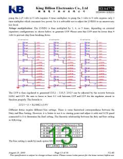
Following table is the setting for MO_LIO?[...] and MO_?PP[...] and others related to LCD display
setting and pin assignment features.
MO_LIO?[…] MO_?PP[...]
I/O Port
LCD Pin
0
0
1
1
0
1
0
1
Open-drain output
--
Push-pull output
--
xx
--
--
LCD Display
--: Function not available.
xx: Displayable, but may have abnormal leakage current, do not use.
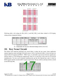
10. Key Scan Circuit
The built-in 4x20 hardware keyboard scan circuit helps to reduce the pin counts where application
requires large key matrix and high LCD pixel count as well as the firmware effort. As key-scan pins are
shared with LCD segment and PRTC4 ~ PRTC7 pins, it is advisable to put resistors between segment pins
and key matrix to avoid shorting the segment pins when two or more keys in the same row are pressed
simultaneously. Two key can be detected simultaneously and the first detected key code is stored in
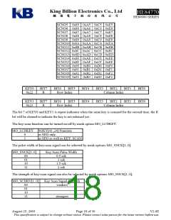
KEY0 register and the second in KEY1 register respectively. The key code for each key location is listed
in the following table.
Key Loc SCNI0 SCNI1 SCNI2 SCNI3
SCNO0 0x80 0xA0 0xC0 0xE0
SCNO1 0x81 0xA1 0xC1 0xE1
SCNO2 0x82 0xA2 0xC2 0xE2
SCNO3 0x83 0xA3 0xC3 0xE3
SCNO4 0x84 0xA4 0xC4 0xE4
August 25, 2003
Page 17 of 30
V2.6E
This specification is subject to change without notice. Please contact sales person for the latest version before use.

 KB [ King blillion Electronics Co.,Ltd. ]