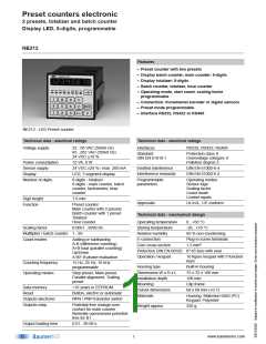
Preset counters electronic
2 presets, totalizer and batch counter
Display LED, 8-digits, programmable
NE212
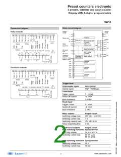
Block circuit diagram
Connection diagram
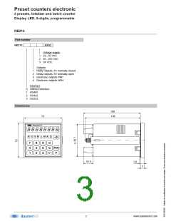
Voltage
supply
Sensor
supply
-
Relay outputs
-
2
3
19
20
26 25 24 23
22 21 20 19 18 17 16 15 14 13 12
+
+
Totalizer
Signal input
A
12
13
Output
P2
B
A
+24V 0V
A 90° B
4
5
6
7
8
9
Main counter with
2 presets
start count
B
Count
Reset
14
15
RS422
RS232
RS485
scaling factor
Stop/Hold
P2
B1
Batch counter as
preselectioncounter
with 1 preset
XB-signal-
input
16
17
max. 265 V
terminal - terminal /
- terminal
multiplier
tachometer or
batch counter
XB-reset
10
11
11 10
9
8
7
6
5
4
3
2
1
Coding for
input logic
Operating
time meter
NPN Br. 18-20
PNP Br. 18-19
18
B1
P2
P1
21
22
T,R-
T,R+
Interface
RS485
TxD+ 23
TxD- 24
RxD+ 25
Interface
RS422
Electronic outputs
26
26 25 24 23
22 21 20 19 18 17 16 15 14 13 12
RxD-
23
25
26
TxD
RxD
GND
Interface
RS232
B
A
+24V 0V
Count
RS422
RS232
RS485
Trigger level
Optocoupler inputs
Control inputs
Input circuit
max. 265 V
terminal - terminal /
- terminal
PNP- / NPN-logic
11 10
9
8
7
6
5
4
3
2
1
Count input
B1
P2
P1
Trigger current
Switch-off current
Input resistance
Reset input
9...16 mA
<0.5 mA
1.65 kΩ
Output
Trigger current
Switch-off current
Input resistance
5...8 mA
<0.5 mA
3.3 kΩ
Relay outputs
Output circuit
250 VAC / 110 VDC
1 A
Switching voltage max.
Switching current max.
Switching capacity max.
Relay responding time
150 VA / 30 W
5 ms
Electronical outputs
Output circuit
PNP-switching transistor Open collector
Switching voltage
24 VDC ±20 %
Switching current max.
10 mA (AC)
50 mA (DC)
NPN-switching transistor Open collector
Switching voltage max.
Switching current max.
35 V
50 mA
www.baumerivo.com
2

 IVO [ BAUMER IVO GMBH & CO. KG ]