Positions
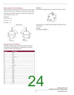
Alternative Insert Positions
Indicates location of centerline of key or keyway of shells in fixed
normal position. Insert is rotated as shown by arrow and letters.
View shows mating side of pin or termination side of socket.
Connectors according to VG95234 are generally available with
insert positions X and Y only.
Tolerances:
# 10SL-20: ± 2°
# 22-36: ± 1,5°
# 32A69: ± 1°
Normal position
Insert positions are added without hyphen directly behind the
contact type.
Example:
CA3106F32A10P 2 -B-01
Socket
Pin
Mating face
Mating face
Special Insert Positions
A number of layouts allow for additional insert alternations.
These special insert alternations are identified by a position
number as shown in the table below.
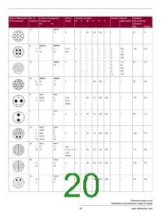
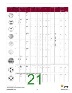
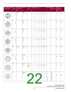
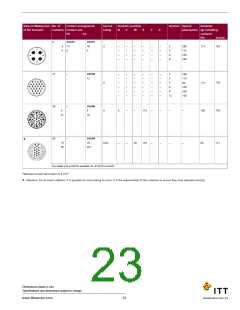
Position
2
Polarization
260°
3
110°
4
80°
5
use pos. 3
85°
6
8
250°
9
280°
11
12
13
14
15
16
17
18
19
20
21
22
23
24
25
26
105°
100°
use pos. 8
30°
45°
120°
130°
150°
195°
220°
255°
290°
165°
330°
235°
125°
Dimensions shown in mm
Specifications and dimensions subject to change
24
www.ittcannon.com

 ITT [ ITT Cannon ]