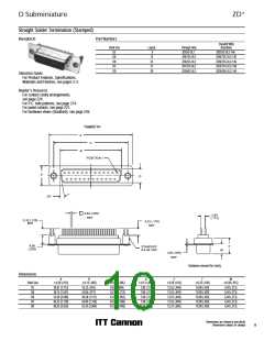
D Subminiature
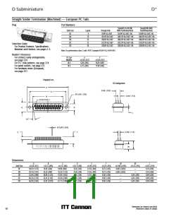
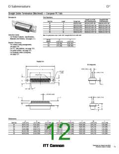
D*
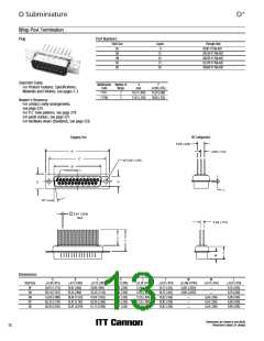
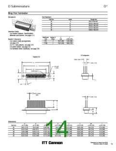
Wrap Post Termination
Receptacle
Part Numbers
Shell Size
Layout
9
Through Hole
DE
DA
DB
DC
DD
DE9S-F179A-A197
DA15S-F179A-A197
DB25S-F179A-A197
DC37S-F179A-A197
DD50S-F179A-A197
15
25
37
50
Selection Guide
ɀ For Product Features, Specifications,
Materials and Finishes, see pages 2-3.
Modification Number of
X
max.
Y
Code
Wraps
0,89 (.035)
Reader’s Resource
ɀ For contact cavity arrangements,
see page 224.
F179
2
3
10,21 (.402)
13,61 (.536)
15,20 (.598)
18,60 (.732)
F179A
ɀ For P.C. hole patterns, see page 274.
ɀ For panel cutouts, see page 221.
ɀ For hardware views (Standard), see page 226.
DD Configuration
Engaging Face
5,69 (.224)
A
2,84 (.112)
C
Ø 3,05
(.120)
B
POSITION 1
D
E
L
10°
0,61 (.024)
REF
2.84 (.112)
X
Y
F
W
Dimensions
A
B
C
D
E
F
W
L
Shell Size
DE
0,13 (.005)
0,13 (.005)
0,13 (.005)
0,13 (.005)
0,38 (.015)
0,25 (.010)
0,38 (.015)
0,25 (.010)
0,76 (.030)
0,76 (.030)
0,76 (.030)
0,76 (.030)
0,76 (.030)
30,81 (1.213)
39,14 (1.541)
53,04 (2.088)
69,32 (2.729)
66,93 (2.635)
16,33 (.643)
24,66 (.971)
38,38 (1.511)
54,84 (2.159)
52,42 (2.064)
24,99 (.984)
33,32 (1.312)
47,04 (1.852)
63,50 (2.500)
61,11 (2.406)
7,90 (.311)
7,90 (.311)
7,90 (.311)
7,90 (.311)
10,74 (.423)
12,55 (.494)
12,55 (.494)
12,55 (.494)
12,55 (.494)
15,37 (.605)
10,90 (.429)
10,90 (.429)
10,90 (.429)
10,90 (.429)
10,90 (.429)
6,94 (.273)
6,94 (.273)
6,94 (.273)
6,94 (.273)
6,94 (.273)
DA
DB
DC
DD
Dimensions are shown in mm (inch)
Dimensions subject to change
13

 ITT [ ITT Cannon ]