D Subminiature
Combo D
ɍ
ɍɍ
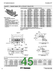
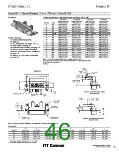
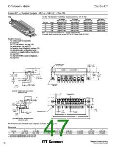
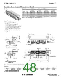
Coaxial 90° — Standard Footprint .318 or .283 inch (Sizes DE-DC)
Receptacle
75 Ohm Part Numbers* with Metal Bracket and Rivnut # 4-40 UNC
Part Number
Without Screw Locks
Without Boardlocks
Part Number
Without Screw Locks
With Boardlocks
Part Number
With Screw Locks
Without Boardlocks
Part Number
With Screw Locks
With Boardlocks
Shell Size
DE
Layout
5W1
DEMP5C1SJA197
DAMP7C2SJA197
DAMP11C1SJA197
DAMP3C3SJA197
DAMP3CK3SJA197TM
DBMP5C5SJA197
DBMP9C4SJA197
DBMP13C3SJA197
DBMP17C2SJA197
DBMP21C1SJA197
DCMP8C8SJA197
DCMP13C6SJA197
DCMP17C5SJA197
DCMP21CA4SJA197
DCMP25C3SJA197
DCMP27C2SJA197
DEMC5C1SJA197
DAMC7C2SJA197
DAMC11C1SJA197
DAMC3C3SJA197
DAMC3CK3SJA197TM
DBMC5C5SJA197
DBMC9C4SJA197
DBMC13C3SJA197
DBMC17C2SJA197
DBMC21C1SJA197
DCMC8C8SJA197
DCMC13C6SJA197
DCMC17C5SJA197
DCMC21CA4SJA197
DCMC25C3SJA197
DCMC27C2SJA197
DEMD5C1SJA197
DAMD7C2SJA197
DAMD11C1SJA197
DAMD3C3SJA197
DAMD3CK3SJA197TM
DBMD5C5SJA197
DBMD9C4SJA197
DBMD13C3SJA197
DBMD17C2SJA197
DBMD21C1SJA197
DCMD8C8SJA197
DCMD13C6SJA197
DCMD17C5SJA197
DCMD21CA4SJA197
DCMD25C3SJA197
DCMD27C2SJA197
DEMG5C1SJA197
DAMG7C2SJA197
DAMG11C1SJA197
DAMG3C3SJA197
DAMG3CK3SJA197TM
DBMG5C5SJA197
DBMG9C4SJA197
DBMG13C3SJA197
DBMG17C2SJA197
DBMG21C1SJA197
DCMG8C8SJA197
DCMG13C6SJA197
DCMG17C5SJA197
DCMG21CA4SJA197
DCMG25C3SJA197
DCMG27C2SJA197
DA
DA
DA
DA
DB
7W2
11W1
3W3
3WK3ឮ
5W5
DB
9W4
Reader’s Resource
ɀ For contact cavity arrangements,
see page 223.
ɀ For P.C. hole patterns, see pages 231-232.
ɀ For panel cutouts, see page 221.
ɀ For hardware views (Standard), see page 226.
ɀ For alternate bracket configuration (when
connectors are supplied without boardlocks),
see page 226.
DB
13W3
17W2
21W1
8W8
DB
DB
DC
DC
13W6
17W5
21WA4
25W3
27W2
DC
DC
DC
ɀ For alternate 50 Ohm coaxial configuration,
see page 225.
DC
Notes: * For 50 Ohm Coaxial substitute X for C. Example: DEMP5X1SJA197
For contacts with 30 microinches gold substitute K126 for A197. Example: DEMP5C1SJK126
For DD Shell Sizes, see page 47.
ឮ Keyed.
0,56
(.023)
Ø 0,51
(.020)
Engaging Face
3,89 (.153)
MIN
A
2,54
(.100)
C
B
11,94 ± 0,33
(.470 ± .013)
D
E
L
2,92
(.115)
Screw lock, boardlock and signal contacts
removed for clarity
10°
BOARDLOCK
Ø 0,76
(.030)
0,79
(.031)
2,84
(.112)
4,33 ± 0,38
(.170 ± .015)
BRACKET,
METAL
12,34
(.486)
RIVNUT
#4-40 UNC
8,64
(.340)
7,18 ± 0,25
(.283 ± .010)
F
W
SCREW LOCK
#4-40 UNC
6,50 ± 0,25
(.256 ± .010)
Screw lock, boardlock and coaxial contact
removed for clarity
Note: ɋ Dimension varies with alternate bracket configuration, See Reader’s Resource page 226.
Dimensions
A
B
C
D
E
F
W
L
Shell Size
DE
0,38 (.015)
0,13 (.005)
0,13 (.005)
0,13 (.005)
0,38 (.015)
0,25 (.010)
10,90 (.429)
10,90 (.429)
10,90 (.429)
10,90 (.429)
0,38 (.015)
6,94 (.273)
6,94 (.273)
6,94 (.273)
6,94 (.273)
0,25 (.010)
30,81 (1.213)
39,14 (1.541)
53,04 (2.088)
69,32 (2.729)
16,33 (.643)
24,66 (.971)
38,38 (1.511)
54,84 (2.159)
24,99 (.984)
33,32 (1.312)
47.04 (1.852)
63,50 (2.500)
7,90 (.311)
7,90 (.311)
7,90 (.311)
7,90 (.311)
12,55 (.494)
12,55 (.494)
12,55 (.494)
12,55 (.494)
0,76 (.030)
0,76 (.030)
0,76 (.030)
0,76 (.030)
DA
DB
DC
ɍ Connector footprint measured from the front shell.
ɍɍ Connector footprint measured from the rear shell.
Dimensions are shown in mm (inch)
Dimensions subject to change
45

 ITT [ ITT Cannon ]