D Subminiature
D*M
ɍ
ɍɍ
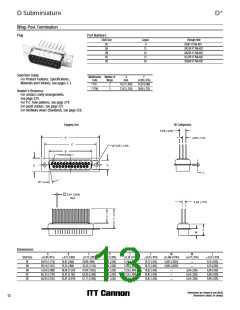
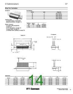
90° Solder Termination (Machined) — Standard Footprint .318 or .283 inch
Plug
Part Numbers
Bracket,
Bracket &
Screw Lock
# 4-40 UNC
Boardlock &
Screw Lock
# 4-40 UNC
Bracket &
Boardlock
Shell Size
DE
Layout
9
Bracket
DEMP9PJK87
DAMP15PJK87
DBMP25PJK87
DCMP37PJK87
DDMP50PJK87
DEMCP9PJK87
DAMC15PJK87
DBMC25PJK87
DCMC37PJK87
DDMC50PJK87
DEMD9PJK87
DAMD15PJK87
DBMD25PJK87
DCMD37PJK87
DDMD50PJK87
DEMG9PJK87
DAMG15PJK87
DBMG25PJK87
DCMG37PJK87
DDMG50PJK87
DA
15
DB
25
DC
37
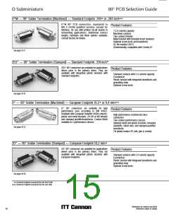
Selection Guide
ɀ For Product Features, Specifications,
Materials and Finishes, see pages 14-15.
DD
50
Note: For contacts with 30 microinches gold substitute K127 for K87. Example: DAMG15PJK127
Reader’s Resource
ɀ For contact cavity arrangements,
see page 224.
ɀ For P.C. hole patterns, see page 272.
ɀ For panel cutouts, see page 221.
ɀ For hardware views (Standard), see page 226.
ɀ For alternate bracket configuration (when
connectors are supplied without boardlocks),
see page 226.
DD Configuration
Engaging Face
2,84
A
C
B
(.112)
4,33 ± 0,38
(.170 ± .015)
5,68
(.224)
E
D
7,18 ± 0,25
(.283 ± .010)
2,92
(.115)
10°
L
Ø 0,76
(.030)
BOARDLOCK
Screw lock and boardlock
removed for clarity
BRACKET,
METAL
4,33 ± 0,38
(.170 ± .015)
2,84
(.112)
M
N
RIVNUT
#4-40 UNC
7,18 ± 0,25
(.283 ± .010)
F
W
6,50 ± 0,25
(.256 ± .010)
SCREW LOCK
#4-40 UNC
Screw lock and boardlock
removed for clarity
Note: ɋ Dimension varies with alternate bracket configuration. See Reader’s Resource page 226.
Dimensions
A
B
C
D
E
F
W
W
L
M
N
Shell Size
DE
0,38 (.015)
0,13 (.005)
0,13 (.005)
0,13 (.005)
0,38 (.015)
0,25 (.010)
0,368 (.0145)
0,41 (.016)
0,25 (.010)
0,25 (.010)
12,34 (.486)
12,34 (.486)
12,34 (.486)
12,34 (.486)
13,74 (.541)
0,25 (.010)
30,81 (1.213) 16,92 (.666)
39,14 (1.541) 25,25 (.994)
24,99 (.984)
8,36 (.329)
8,36 (.329)
8,36 (.329)
8,36 (.329)
11,07 (.436)
12,55 (.494)
12,55 (.494)
12,55 (.494)
12,55 (.494)
15,37 (.605)
10,72 (.422)
10,72 (.422)
10,82 (.426)
10,82 (.426)
10,82 (.426)
6,693 (.2635)
—
0,76 (.030)
0,76 (.030)
0,99 (.039)
0,99 (.039)
0,99 (.039)
8,64 (.340)
8,64 (.340)
8,64 (.340)
8,64 (.340)
10,06 (.396)
DA
33,32 (1.312)
6,693 (.2635)
—
DB
53,04 (2.088) 38,96 (1.534) 47,04 (1.852)
69,32 (2.729) 55,42 (2.182) 63,50 (2.500)
66,93 (2.635) 52,81 (2.079) 61,11 (2.406)
—
—
—
6,84 (.269)
6,84 (.269)
6,84 (.269)
DC
DD
ɍ Connector footprint measured from the front shell.
ɍɍ Connector footprint measured from the rear shell.
Dimensions are shown in mm (inch)
Dimensions subject to change
16

 ITT [ ITT Cannon ]