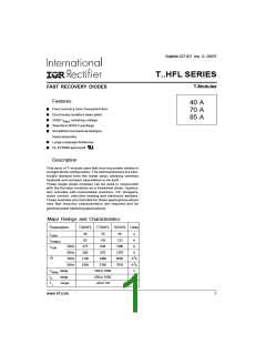
T..HFL Series
Bulletin I27107 rev. A 09/97
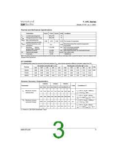
Thermal and Mechanical Specifications
Parameters
T40HFL T70HFL T85HFL Units Conditions
TJ
Tstg
Junctionoperatingtemp.
-40to125
-40to150
oC
oC
Storage temperature range
RthJC Max.internalthermal
resistancejunctiontocase
RthC-S Thermalresistance, case
toheatsink
0.85
0.53
0.46
K/W Permodule,DCoperation
Mountingsurfaceflat,smoothandgreased.
K/W
0.2
Permodule
T
Mounting
Baseto
1.3±10%
Nm M3.5mountingscrews(2)
torque±10% heatsink
BusbartoTerminal
Non-lubricated threads
Nm M5screwsterminals;non-lubricatedthreads
3±10%
54 (19)
D-56
wt
Approximateweight
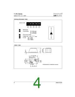
Casestyle
g (oz) See outline table
T-MODULE
(2) A mounting compound is recommended and the torque should be rechecked after a period of about 3 hours to allow for the
spread of the compound
∆R Conduction
(The following table shows the increment of thermal resistance RthJC when devices operate at different conduction angles than DC)
Sinusoidal conduction @ TJ max.
Rectangular conduction @ TJ max.
Devices
Units
180o
0.06
0.05
0.04
120o
0.08
0.06
0.05
90o
60o
30o
180o
0.05
0.04
0.03
120o
0.08
0.06
0.05
90o
60o
30o
T40HFL
T70HFL
T85HFL
0.10
0.08
0.06
0.14
0.11
0.09
0.24
0.19
0.15
0.10
0.08
0.07
0.15
0.12
0.09
0.24 K/W
0.19
0.015
Reverse Recovery Characteristics
T40HFL
T70HFL
T85HFL
Parameter
Units
Conditions (*)
S02 S05 S10 S02 S05 S10 S02 S05 S10
trr Maximum reverse
recovery time
TJ = 25 °C, -diF/dt = 100A/µs
IF = 1 A to VR = 30V
70 110 270 70 110 270 80 120 290 ns
200 500 1000 200 500 1000 200 500 1000 ns
TJ = 25 °C, -diF/dt = 25A/µs
IFM = π x rated IF(AV),VR = -30 V
Qrr Maximum reverse
recovered charge
TJ = 25 °C, -diF/dt = 100A/µs
IF = 1 A to VR = 30V
0.25 0.4 1.35 0.25 0.4 1.35 0.3 0.6 1.6
0.55 2.0 8.0 0.6 2.1 8.5 0.8 3.5 1.5
µC
µC
TJ = 25 °C, -diF/dt = 25A/µs
IFM = π x rated IF(AV)VR = -30 V
(*) Tested on LEM 300A Diodemeter Tester
3
www.irf.com

 INFINEON [ Infineon ]