Data Sheet No. PD60147 rev.
U
IR2110(-1-2)(S)PbF/IR2113(-1-2)(S)PbF
HIGH AND LOW SIDE DRIVER
Features
Product Summary
• Floating channel designed for bootstrap operation
Fully operational to +500V or +600V
Tolerant to negative transient voltage
dV/dt immune
V
(IR2110) 500V max.
OFFSET
(IR2113) 600V max.
I +/-
O
2A / 2A
10 - 20V
• Gate drive supply range from 10 to 20V
• Undervoltage lockout for both channels
• 3.3V logic compatible
V
OUT
Separate logic supply range from 3.3V to 20V
t
(typ.)
120 & 94 ns
on/off
Logic and power ground 5V offset
• CMOS Schmitt-triggered inputs with pull-down
• Cycle by cycle edge-triggered shutdown logic
• Matched propagation delay for both channels
• Outputs in phase with inputs
Delay Matching (IR2110) 10 ns max.
(IR2113) 20ns max.
Packages
Description
The IR2110/IR2113 are high voltage, high speed power MOSFET and
IGBT drivers with independent high and low side referenced output chan-
nels. Proprietary HVIC and latch immune CMOS technologies enable
ruggedized monolithic construction. Logic inputs are compatible with
standard CMOS or LSTTL output, down to 3.3V logic. The output
drivers feature a high pulse current buffer stage designed for minimum
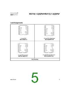
16-Lead SOIC
IR2110S/IR2113S
14-Lead PDIP
IR2110/IR2113
driver cross-conduction. Propagation delays are matched to simplify use in high frequency applications. The
floating channel can be used to drive an N-channel power MOSFET or IGBT in the high side configuration which
operates up to 500 or 600 volts.
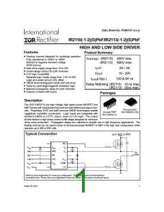
Typical Connection
ꢃꢄꢅꢆꢇꢅꢈꢉꢉꢊꢅꢇꢋꢅꢌꢉꢉꢊ
ꢀꢎ
ꢊ
ꢊ
ꢊ
ꢊ
ꢑꢑ
ꢑꢑ
ꢒ
ꢓ
ꢀꢁꢂ
ꢓꢑ
ꢀꢁꢂ
ꢓꢑ
ꢍꢎ
ꢏꢎꢐꢑ
ꢏꢁꢂ
ꢊ
ꢔꢔ
ꢏꢁꢂ
ꢊ
ꢔꢎꢕ
ꢊ
ꢓꢓ
ꢓꢓ
ꢏꢎ
ꢊ
ꢔꢔ
(Refer to Lead Assignments for correct pin configuration). This/These diagram(s) show electrical
connections only. Please refer to our Application Notes and DesignTips for proper circuit board layout.
www.irf.com
1

 INFINEON [ Infineon ]