FILE NAME: B100 RevB.DOC, REVISION: January 19, 2007 V15
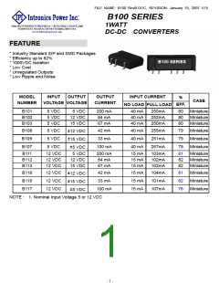
SPECIFICATIONS
℃
All Specifications Typical At Nominal Line, Full Load, and 25 Unless Otherwise Noted
INPUT SPECIFICATIONS :
GENERAL SPECIFICATIONS :
Input Voltage Range....……………................................................10%
Input Filter ……………………………………………..………Capacitive
Efficiency...........................................………..…………............See Table
Isolation Voltage...................................……..……….........1000 VDC min.
Isolation Resistance .....................…….………….………10^9 Ohms min.
Switching Frequency .............................……......................100KHz typ.
℃
℃
to +85
OUTPUT SPECIFICATIONS :
Operating Ambient Temperature Range...………...…….... -40
±
℃
…………..……… Linearly to Zero power at 100
℃
Voltage Accuracy…………………....……………….........… 3.0% max.
De-rating, Above 85
℃
Case temperature (Note5)………..………….………..…..…...+100
max.
Ripple and Noise, 20MHz BW....SIP Models......……..75mV p-p max.
SMD Models……....120mV p-p max.
Cooling………………………………………..….………..Natural Convection
℃
℃
to +125
Storage Temperature Range ...…............………....…....... -55
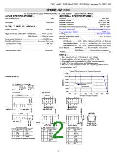
Dimensions:
±
Temperature Coefficient....................….…………....... 0.05%/C max.
Short Circuit Protection...................….…………Momentary 1sec. max.
SIP Models………….0.77 x 0.24 x 0.40inches(19.5 x 6.1 x 10.2mm)
SMD Models(Single)…..0.5 x 0.31 x 0.27inches(12.7 x 8.0 x 6.8mm)
±
Line Regulation, Note1..….………...……………………..... 1.2% max.
SMD Models(Dual)…. 0.6 x 0.31 x 0.27inches(15.24 x 8.0 x 6.8mm)
Case Material………..SIP Models………Non-conductive black plastic
SMD Models………….Epoxy molding compound
±
Load Regulation, Note2…………………..........………….... 10% max.
Weight………..……………………………………………………………..1.8g
NOTE :
1. Line regulation is per 1.0% change in input voltage
2. Load regulation is for load change from 100% to 20%
3. The output noise is measured with 0.33uF ceramic capacitor.
4. Suffix “S” to the model number with SMD packages
5. Maximum case temperature under any operating condition should
℃
.
not be exceeded 100
Typical Derating curve for Natural Convection
120%
100%
80%
60%
40%
20%
0%
Dimensions:
Al l Di mensi ons I n I nches( mm)
Natural
Convection
Tol er ance I nches
Mi l l i met er s
X. X±0. 25
X. XX±0. 01
X. XXX±0. 005 X. XX±0. 13
±0. 002
±0. 05
Pi n
SI P PACKAGES
SMD PACKAGES
-40
-20
0
20
40
60
80
100
Ambient Temperature(oC)
PIN CONNECTION
Pin Single Output Dual Output
PIN CONNECTION
PIN CONNECTION
Single Output
-Vin
Dual Output
-Vin
Pin
1
Pin
1
1
2
4
5
6
+Vin
-Vin
+Vin
-Vin
-Vout
Common
+Vout
2
3
+Vin
No Pin
2
3
+Vin
No Pin
-Vout
No Pin
+Vout
4
5
-Vout
+Vout
4
5
Common
-Vout
6
7
8
No Pin
No Pin
NA
6
7
8
9
10
NA
NA:Not Available for Electrical Connection
+Vout
No Pin
No Pin
NA
- 2 -

 INTRONICS [ INTRONICS POWER, INC. ]