X9313
AC Operating Characteristics Over recommended operating conditions unless otherwise stated.
LIMITS
TYP
SYMBOL
PARAMETER
MIN
100
100
2.9
1
(Note 6)
MAX
UNIT
ns
t
t
t
CS to INC setup
CI
ID
DI
INC HIGH to U/D change
U/D to INC setup
INC LOW period
ns
µs
t
µs
IL
IH
IC
t
t
INC HIGH period
1
µs
INC inactive to CS inactive
CS deselect time (STORE)
CS deselect time (NO STORE)
1
µs
t
t
20
100
ms
ns
CPH
CPH
t
INC to V change
W
1
5
5
µs
IW
t
INC cycle time
4
µs
CYC
t , t (Note 7)
INC input rise and fall time
Power-up to wiper stable
500
5
µs
R
F
t
(Note 7)
µs
PU
t
V
(Note 7)
V
power-up rate
0.2
50
10
V/ms
ms
R
CC
CC
Store cycle
t
WR
NOTES:
6. Typical values are for T = 25°C and nominal supply voltage.
A
7. This parameter is not 100% tested.
spec is always in effect. In order to prevent unwanted tap
position changes, or an inadvertent store, bring the CS and
Power-Up and -Down Requirements
The recommended power-up sequence is to apply V /V
CC SS
INC high before or concurrently with the V
up.
pin on power-
CC
first, then the potentiometer voltages. During power-up, the
data sheet parameters for the DCP do not fully apply until 1
millisecond after V
reaches its final value. The V ramp
CC
CC
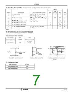
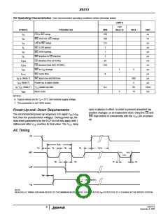
AC Timing
CS
t
CYC
t
t
t
t
t
CPH
CI
IL
IH
IC
90%
90%
INC
U/D
10%
t
t
t
t
R
ID
DI
F
t
IW
(SEE NOTE)
MI
V
W
NOTE:
MI IN THE AC TIMING DIAGRAM REFERS TO THE MINIMUM INCREMENTAL CHANGE IN THE V OUTPUT DUE TO A CHANGE IN THE WIPER POSITION.
W
FN8177.2
8
September 9, 2005

 INTERSIL [ Intersil ]