X9313
DC Operating Characteristics Over recommended operating conditions unless otherwise stated.
LIMITS
TYP
SYMBOL
PARAMETER
active current
TEST CONDITIONS/NOTES
MIN
(Note 4)
MAX
UNIT
I
V
CS = V , U/D = V or V and INC =
1
3
mA
CC
CC
IL IL IH
0.42 / 2.4V @ max t
CYC
I
Standby supply current
CS = V
CC
- 0.3V, U/D and INC = V or
SS
200
500
µA
SB
CC
- 0.3V
V
I
CS, INC, U/D input leakage current
CS, INC, U/D input HIGH current
CS, INC, U/D input LOW current
CS, INC, U/D input capacitance
V
= V to V
SS CC
±10
µA
V
LI
IN
V
2
V
+ 1
CC
IH
V
-1
+0.8
V
IL
C
V
= 5V, V = V , TA = 25°C,
10
pF
IN
CC
IN
SS
f = 1MHz
NOTES:
4. Typical values are for TA = 25°C and nominal supply voltage.
5. This parameter is periodically sampled and not 100% tested.
Endurance and Data Retention
PARAMETER
MIN
UNIT
Minimum endurance
100,000
Data changes per bit
per register
Data retention
100
Years
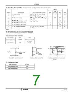
V /R
H
H
R
TOTAL
V /R
H
H
TEST POINT
/R
R
R
L
H
C
L
C
W
C
H
10pF
V
S
V
VW
TEST POINT
/R
W
W
25pF
FORCE
CURRENT
V
W
W
10pF
V /R
L
L
V /R
R
L
L
W
FIGURE 1. TEST CIRCUIT #1
FIGURE 2. TEST CIRCUIT #2
FIGURE 3. CIRCUIT #3 SPICE MACRO
MODEL
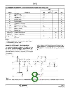
AC Conditions of Test
Input pulse levels
Input rise and fall times
Input reference levels
0V to 3V
10ns
1.5V
FN8177.2
September 9, 2005
7

 INTERSIL [ Intersil ]