MUR3040PT, RURH1540CC, MUR3060PT, RURH1560CC
o
Electrical Specifications (Per Leg) T = 25 C, Unless Otherwise Specified
C
MUR3040PT, RURH1540CC
MUR3060PT, RURH1560CC
SYMBOL
TEST CONDITION
MIN
TYP
MAX
1.25
1.12
100
-
MIN
TYP
MAX
1.5
1.2
-
UNITS
V
V
I
I
= 15A
-
-
-
-
-
-
-
-
-
-
-
-
-
-
-
-
-
-
-
-
-
-
-
-
-
-
F
F
o
= 15A, T = 150 C
V
F
C
I
V
V
V
V
= 400V
= 600V
-
-
µA
µA
µA
µA
ns
R
R
R
R
R
-
-
100
-
o
= 400V, T = 150 C
C
-
500
-
-
o
= 600V, T = 150 C
-
-
500
55
60
-
C
t
I
I
I
I
= 1A, dI /dt = 100A/µs
-
55
60
-
-
rr
F
F
F
F
F
= 15A, dI /dt = 100A/µs
-
-
ns
F
t
t
= 15A, dI /dt = 100A/µs
30
17
-
30
20
-
ns
a
F
= 15A, dI /dt = 100A/µs
-
-
ns
b
F
o
R
1.5
1.5
C/W
θJC
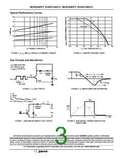
DEFINITIONS
V
= Instantaneous forward voltage (pw = 300µs, D = 2%).
F
I
= Instantaneous reverse current.
R
t
= Reverse recovery time at dI /dt = 100A/µs (See Figure 6), summation of t + t .
F a b
rr
t
= Time to reach peak reverse current at dI /dt = 100A/µs (See Figure 6).
F
a
t
= Time from peak I
RM
to projected zero crossing of I
RM
based on a straight line from peak I
through 25% of I
(See Figure 6).
b
RM
RM
R
= Thermal resistance junction to case.
θJC
pw = pulse width.
D = duty cycle.
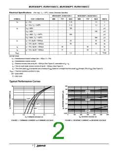
Typical Performance Curves
80
500
100
o
175 C
10
1.0
o
175 C
10
o
100 C
o
0.1
100 C
o
25 C
0.01
0.001
o
25 C
1
0
100
200
300
400
500
600
0
0.5
1.0
1.5
2.0
V , REVERSE VOLTAGE (V)
V , FORWARD VOLTAGE (V)
F
R
FIGURE 1. FORWARD CURRENT vs FORWARD VOLTAGE
FIGURE 2. REVERSE CURRENT vs REVERSE VOLTAGE
2

 INTERSIL [ Intersil ]