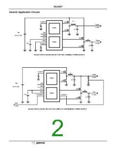
ISL6227
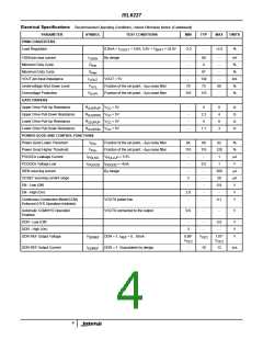
Electrical Specifications Recommended Operating Conditions, Unless Otherwise Noted. (Continued)
PARAMETER
SYMBOL
TEST CONDITIONS
MIN
TYP
MAX
UNITS
PWM CONVERTERS
Load Regulation
0.0mA < I
By design
< 5.0A; 5.0V < V
< 24.0V
BATT
-2.0
-
+2.0
%
VOUT1
VSEN pin bias current
I
-
-
80
4
-
-
nA
%
VSEN
Minimum Duty Cycle
D
min
Maximum Duty Cycle
D
-
87
-
%
max
VOUT pin input impedance
Undervoltage Shut-Down Level
Overvoltage Protection
I
VOUT = 5V
-
134
75
-
kΩ
%
VOUT
V
Fraction of the set point; ~2µs noise filter
Fraction of the set point; ~2µs noise filter
70
110
80
-
UVL
V
115
%
OVP1
GATE DRIVERS
Upper Drive Pull-Up Resistance
Upper Drive Pull-Down Resistance
Lower Drive Pull-Up Resistance
Lower Drive Pull-Down Resistance
R
V
V
V
V
= 5V
= 5V
= 5V
= 5V
-
-
-
-
4
8
4
8
3
Ω
Ω
Ω
Ω
2UGPUP
CC
CC
CC
CC
R
2.3
4
2UGPDN
R
R
2LGPUP
1.1
2LGPDN
POWER GOOD AND CONTROL FUNCTIONS
Power Good Lower Threshold
Power Good Higher Threshold
PGOODx Leakage Current
PGOODx Voltage Low
ISEN sourcing current
OCSET sourcing current range
EN - Low (Off)
V
Fraction of the set point; ~3µs noise filter
Fraction of the set point; ~3µs noise filter.
84
89
92
120
1
%
%
µA
V
PG-
V
110
115
PG+
I
V
= 5.5V
-
-
-
PGLKG
PULLUP
= -4mA
PGOOD
V
I
0.5
1
PGOOD
By design
-
-
-
-
-
-
260
20
0.8
-
µA
µA
V
2
-
EN - High (On)
2.0
-
V
Continuous-Conduction-Mode(CCM)
Enforced (HYS Operation Inhibited)
VOUTX pulled low
0.1
V
Automatic CCM/HYS Operation
Enabled
VOUTX connected to the output
0.9
-
-
V
DDR - Low (Off)
-
3
-
-
0.8
-
V
V
V
DDR - High (On)
DDR REF Output Voltage
V
DDR = 1, I
= 0...10mA
0.99*
OC2
V
1.01*
DDREF
REF
OC2
V
V
OC2
DDR REF Output Current
I
DDR = 1. Guaranteed by design.
-
10
12
mΑ
DDREF
4

 INTERSIL [ Intersil ]