ISL3150E, ISL3152E, ISL3153E, ISL3155E, ISL3156E, ISL3158E
Mini Small Outline Plastic Packages (MSOP)
N
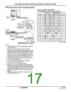
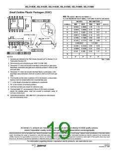
M10.118 (JEDEC MO-187BA)
10 LEAD MINI SMALL OUTLINE PLASTIC PACKAGE
INCHES
MILLIMETERS
E1
E
SYMBOL
MIN
MAX
MIN
0.94
0.05
0.75
0.18
0.09
2.95
2.95
MAX
1.10
0.15
0.95
0.27
0.20
3.05
3.05
NOTES
A
A1
A2
b
0.037
0.002
0.030
0.007
0.004
0.116
0.116
0.043
0.006
0.037
0.011
0.008
0.120
0.120
-
-B-
0.20 (0.008)
INDEX
AREA
1 2
A
B
C
-
-
TOP VIEW
4X θ
9
0.25
(0.010)
R1
c
-
R
GAUGE
PLANE
D
3
E1
e
4
SEATING
PLANE
L
0.020 BSC
0.50 BSC
-
-C-
4X θ
L1
A
A2
E
0.187
0.016
0.199
0.028
4.75
0.40
5.05
0.70
-
L
6
SEATING
PLANE
L1
N
0.037 REF
10
0.95 REF
10
-
0.10 (0.004)
-A-
C
C
b
7
-H-
A1
e
R
0.003
0.003
-
-
0.07
0.07
-
-
-
D
0.20 (0.008)
C
R1
θ
-
o
o
o
o
a
SIDE VIEW
5
15
5
15
-
C
L
o
o
o
o
0
6
0
6
-
α
E
1
-B-
Rev. 0 12/02
0.20 (0.008)
C
D
END VIEW
NOTES:
1. These package dimensions are within allowable dimensions of
JEDEC MO-187BA.
2. Dimensioning and tolerancing per ANSI Y14.5M-1994.
3. Dimension “D” does not include mold flash, protrusions or gate
burrs and are measured at Datum Plane. Mold flash, protrusion
and gate burrs shall not exceed 0.15mm (0.006 inch) per side.
4. Dimension “E1” does not include interlead flash or protrusions
- H -
and are measured at Datum Plane.
Interlead flash and
protrusions shall not exceed 0.15mm (0.006 inch) per side.
5. Formed leads shall be planar with respect to one another within
0.10mm (.004) at seating Plane.
6. “L” is the length of terminal for soldering to a substrate.
7. “N” is the number of terminal positions.
8. Terminal numbers are shown for reference only.
9. Dimension “b” does not include dambar protrusion. Allowable
dambar protrusion shall be 0.08mm (0.003 inch) total in excess
of “b” dimension at maximum material condition. Minimum space
between protrusion and adjacent lead is 0.07mm (0.0027 inch).
- B -
-A -
10. Datums
and
to be determined at Datum plane
.
- H -
11. Controlling dimension: MILLIMETER. Converted inch dimen-
sions are for reference only
FN6363.0
December 14, 2006
17

 INTERSIL [ Intersil ]