EL7202, EL7212, EL7222
Absolute Maximum Ratings (T = 25°C)
A
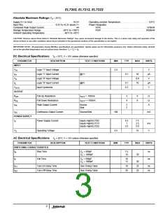
Supply (V+ to Gnd) . . . . . . . . . . . . . . . . . . . . . . . . . . . . . . . . . 16.5V
Input Pins. . . . . . . . . . . . . . . . . . . . . . . . . . -0.3V to +0.3V above V+
Combined Peak Output Current. . . . . . . . . . . . . . . . . . . . . . . . . . .4A
Storage Temperature Range . . . . . . . . . . . . . . . . . .-65°C to +150°C
Ambient Operating Temperature . . . . . . . . . . . . . . . .-40°C to +85°C
Operating Junction Temperature . . . . . . . . . . . . . . . . . . . . . . . 125°C
Power Dissipation
SOIC . . . . . . . . . . . . . . . . . . . . . . . . . . . . . . . . . . . . . .570mW
PDIP . . . . . . . . . . . . . . . . . . . . . . . . . . . . . . . . . . . . .1050mW
CAUTION: Stresses above those listed in “Absolute Maximum Ratings” may cause permanent damage to the device. This is a stress only rating and operation of the
device at these or any other conditions above those indicated in the operational sections of this specification is not implied.
IMPORTANT NOTE: All parameters having Min/Max specifications are guaranteed. Typical values are for information purposes only. Unless otherwise noted, all tests
are at the specified temperature and are pulsed tests, therefore: T = T = T
A
J
C
DC Electrical Specifications T = 25°C, V = 15V unless otherwise specified
A
PARAMETER
INPUT
DESCRIPTION
TEST CONDITIONS
MIN
TYP
MAX
UNITS
V
Logic “1” Input Voltage
2.4
V
µA
V
IH
I
Logic “1” Input Current
Logic “0” Input Voltage
Logic “0” Input Current
Input Hysteresis
@V+
@0V
0.1
10
0.8
10
IH
V
IL
I
0.1
0.3
µA
V
IL
V
HVS
OUTPUT
R
R
Pull-Up Resistance
Pull-Down Resistance
Peak Output Current
I
I
= -100mA
= +100mA
3
4
6
6
Ω
Ω
A
OH
OUT
OUT
OL
I
Source
Sink
2
2
PK
I
Continuous Output Current
Power Supply Current
Source/Sink
100
mA
DC
POWER SUPPLY
I
Inputs High/EL7202
Inputs High/EL7212
Inputs High/EL7222
4.5
1
2.5
7.5
2.5
5.0
S
mA
V
V
Operating Voltage
4.5
15
S
AC Electrical Specifications T = 25°C, V = 15V unless otherwise specified
A
PARAMETER
DESCRIPTION
TEST CONDITIONS
MIN
TYP
MAX
UNITS
SWITCHING CHARACTERISTICS
t
Rise Time
C = 500pF
7.5
10
ns
ns
R
L
C = 1000pF
20
L
t
Fall Time
C = 500pF
10
13
F
L
C = 1000pF
20
25
25
L
t
t
Turn-On Delay Time
Turn-Off Delay Time
See Timing Table
See Timing Table
18
20
ns
ns
D1
D2
3

 INTERSIL [ Intersil ]