Package Mechanical Specifications
3.9
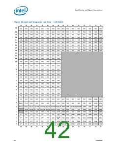
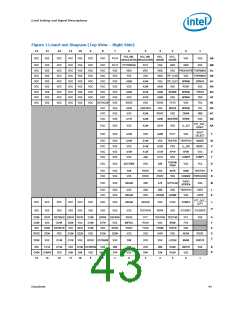
Processor Land Coordinates
Figure 9 shows the top view of the processor land coordinates. The coordinates are
referred to throughout the document to identify processor lands.
.
Figure 9.
Processor Land Coordinates and Quadrants (Top View)
VCC / VSS
30 29 28 27 26 25 24 23 22 21 20 19 18 17 16 15 14 13 12 11 10
9
8
7
6
5
4
3
2
1
AN
AM
AL
AK
AJ
AH
AG
AF
AE
AD
AC
AB
AA
Y
AN
AM
AL
AK
AJ
AH
AG
AF
AE
AD
AC
AB
AA
Y
W
V
W
V
Socket 775 Quadrants
Top View
Address/
Common Clock/
Async
U
U
T
T
R
R
P
P
N
N
M
M
L
L
K
K
J
J
H
H
G
G
F
F
E
E
D
D
C
C
B
B
A
A
30 29 28 27 26 25 24 23 22 21 20 19 18 17 16 15 14 13 12 11 10
9
8
7
6
5
4
3
2
1
VTT / Clocks
Data
§ §
Datasheet
39

 INTEL [ INTEL ]