Boxed Processor Specifications
8.2.2
Boxed Processor Heat Sink Weight
8.2.2.1
Thermal Solution Weight
The 1U passive/2U active combination heat sink solution and the 2U passive heat sink
solution will not exceed a mass of 1050 grams. Note that this is per processor, so a dual
processor system will have up to 2100 grams total mass in the heat sinks. This large
mass will require a minimum chassis stiffness to be met in order to withstand force
during shock and vibration.
See Section 3 for details on the processor weight.
8.2.3
Boxed Processor Retention Mechanism and
Heat Sink Support (CEK)
Baseboards and chassis designed for use by a system integrator should include holes
that are in proper alignment with each other to support the boxed processor. Refer to
the Server System Infrastructure Specification (SSI-EEB 3.6, TEB 2.1 or CEB 1.1).
These specification can be found at: http://www.ssiforum.org.
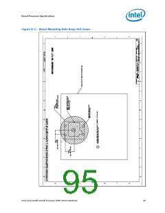
Figure 8-3 illustrates the Common Enabling Kit (CEK) retention solution. The CEK is
designed to extend air-cooling capability through the use of larger heat sinks with
minimal airflow blockage and bypass. CEK retention mechanisms can allow the use of
much heavier heat sink masses compared to legacy limits by using a load path directly
attached to the chassis pan. The CEK spring on the secondary side of the baseboard
provides the necessary compressive load for the thermal interface material. The
baseboard is intended to be isolated such that the dynamic loads from the heat sink are
transferred to the chassis pan via the stiff screws and standoffs. The retention scheme
reduces the risk of package pullout and solder joint failures.
All components of the CEK heat sink solution will be captive to the heat sink and will
only require a Phillips screwdriver to attach to the chassis pan. When installing the
CEK, the CEK screws should be tightened until they will no longer turn easily. This
should represent approximately 8 inch-pounds of torque. Avoid applying more than 10
inch-pounds of torque; otherwise, damage may occur to retention mechanism
components.
8.3
Electrical Requirements
8.3.1
Fan Power Supply (Active CEK)
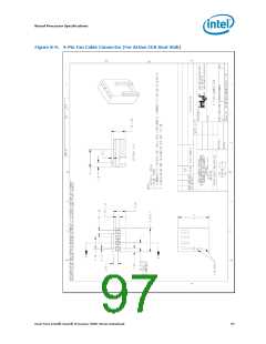
The 4-pin PWM/T-diode controlled active thermal solution is being offered to help
provide better control over pedestal chassis acoustics. This is achieved though more
accurate measurement of processor die temperature through the processor’s
temperature diode (T-diode). Fan RPM is modulated through the use of an ASIC located
on the baseboard that sends out a PWM control signal to the 4th pin of the connector
labeled as Control. This thermal solution requires a constant +12 V supplied to pin 2 of
the active thermal solution and does not support variable voltage control or 3-pin PWM
control. See Table 8-2 for details on the 4-pin active heat sink solution connectors.
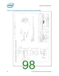
If the 4-pin active fan heat sink solution is connected to an older 3-pin baseboard CPU
fan header it will default back to a thermistor controlled mode, allowing compatibility
with legacy 3-wire designs. When operating in thermistor controlled mode, fan RPM is
automatically varied based on the TINLET temperature measured by a thermistor
located at the fan inlet of the heat sink solution.
Dual-Core Intel® Xeon® Processor 5000 Series Datasheet
99

 INTEL [ INTEL ]