Chipset Configuration Registers
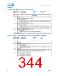
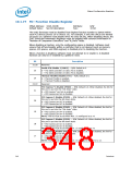
10.1.77 FD—Function Disable Register
Offset Address: 3418–341Bh
Attribute:
Size:
R/W
32-bit
Default Value:
See bit description
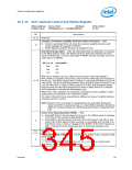
The UHCI functions must be disabled from highest function number to lowest within
each PCI device (Device 29 or Device 26). For example, if only two UHCIs are wanted
on Device 29, software must disable UHCI #3 (UD3 bit set). When disabling UHCIs, the
EHCI Structural Parameters Registers must be updated with coherent information in
“Number of Companion Controllers” and “N_Ports” fields.
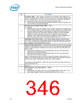
When disabling a function, only the configuration space is disabled. Software must
ensure that all functionality within a controller that is not desired (such as memory
spaces, I/O spaces, and DMA engines) is disabled prior to disabling the function.
When a function is disabled, software must not attempt to re-enable it. A disabled
function can only be re-enabled by a platform reset.
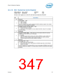
Bit
Description
31:26
Reserved
Serial ATA Disable 2 (SAD2) — R/W. Default is 0.
25
0 = The SATA controller #2 (D31:F5) is enabled.
1 = The SATA controller #2 (D31:F5) is disabled.
Thermal Throttle Disable (TTD) — R/W. Default is 0.
24
0 = Thermal Throttle is enabled.
1 = Thermal Throttle is disabled.
23:22
Reserved
PCI Express* 6 Disable (PE6D) — R/W. Default is 0. When disabled, the link for
this port is put into the “link down” state.
21
20
0 = PCI Express* port #6 is enabled.
1 = PCI Express port #6 is disabled.
PCI Express 5 Disable (PE5D) — R/W. Default is 0. When disabled, the link for
this port is put into the link down state.
0 = PCI Express port #5 is enabled.
1 = PCI Express port #5 is disabled.
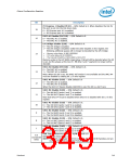
PCI Express 4 Disable (PE4D) — R/W. Default is 0. When disabled, the link for
this port is put into the “link down” state.
19
18
17
0 = PCI Express port #4 is enabled.
1 = PCI Express port #4 is disabled.
NOTE: This bit must be set when Port 1 is configured as a x4.
PCI Express 3 Disable (PE3D) — R/W. Default is 0. When disabled, the link for
this port is put into the link down state.
0 = PCI Express port #3 is enabled.
1 = PCI Express port #3 is disabled.
NOTE: This bit must be set when Port 1 is configured as a x4.
PCI Express 2 Disable (PE2D) — R/W. Default is 0. When disabled, the link for
this port is put into the link down state.
0 = PCI Express port #2 is enabled.
1 = PCI Express port #2 is disabled.
NOTE: This bit must be set when Port 1 is configured as a x4 or a x2.
348
Datasheet

 INTEL [ INTEL ]