Chipset Configuration Registers
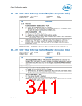
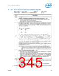
10.1.75 GCS—General Control and Status Register
Offset Address: 3410–3413h
Attribute:
R/W, R/WLO
32-bit
Default Value:
00000yy0h (yy = xx0000x0b)Size:
Bit
Description
31:13
Reserved.
Function Level Reset Capability Structure Select (FLRCSSEL) — R/W.
0 = Function Level Reset (FLR) will utilize the standard capability structure with
unique capability ID assigned by PCISIG.
12
1 = Vendor Specific Capability Structure is selected for FLR.
Boot BIOS Straps (BBS) — R/W. This field determines the destination of accesses
to the BIOS memory range. The default values for these bits represent the strap
values of GNT0# (bit 11) at the rising edge of PWROK and SPI_CS1#(bit 10) at the
rising edge of CLPWROK.
Bits 11:10
0xb
Description
SPI
PCI
LPC
10b
11b
When PCI is selected, the top 16 MB of memory below 4 GB (FF00_0000h to
FFFF_FFFFh) is accepted by the primary side of the PCI P2P bridge and forwarded to
the PCI bus. This allows systems with corrupted or unprogrammed flash to boot from
a PCI device. The PCI-to-PCI bridge Memory Space Enable bit does not need to be set
(nor any other bits) in order for these cycles to go to PCI. Note that BIOS decode
range bits and the other BIOS protection bits have no effect when PCI is selected.
This functionality is intended for debug/testing only.
11:10
When SPI or LPC is selected, the range that is decoded is further qualified by other
configuration bits described in the respective sections.
The value in this field can be overwritten by software as long as the BIOS Interface
Lock-Down (bit 0) is not set.
NOTE: Booting to PCI is intended for debug/testing only. Boot BIOS Destination
Select to LPC/PCI by functional strap or via Boot BIOS Destination Bit will not
affect SPI accesses initiated by Intel Management Engine or Integrated GbE
LAN.
Server Error Reporting Mode (SERM) — R/W.
0 = The Intel® ICH10 is the final target of all errors. The (G)MCH sends a messages
to the ICH for the purpose of generating NMI.
1 = The (G)MCH is the final target of all errors from PCI Express* and DMI. In this
mode, if the ICH10 detects a fatal, non-fatal, or correctable error on DMI or its
downstream ports, it sends a message to the (G)MCH. If the ICH10 receives an
ERR_* message from the downstream port, it sends that message to the
(G)MCH.
9
8:7
6
Reserved
FERR# MUX Enable (FME) — R/W. This bit enables FERR# to be a processor break
event indication.
0 = Disabled.
1 = The ICH10 examines FERR# during a C2, C3, or C4 state as a break event.
See Chapter 5.13.5 for a functional description.
Datasheet
345

 INTEL [ INTEL ]