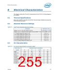
Electrical Characteristics
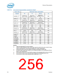
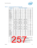
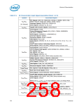
Table 8-4.
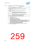
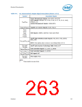
DC Characteristic Input Signal Association (Sheet 2 of 2)
Symbol
Associated Signals
Controller Link: CL_CLK0, CL_DATA0
V
IH_CL/VIL_CL
V
DI / VCM / VSE
USB Signals: USBP[11:0][P,N] (Low-speed and Full-speed)
USB Signals: USBP[11:0][P,N] (in High-speed Mode)
(5 V Tolerant)
VHSSQ / VHSDSC
VHSCM
/
(5 V Tolerant)
Intel® High Definition Audio Signals: HDA_SDIN[3:0]
Strap Signals: HDA_SDOUT, HDA_SYNC (Strap purposes only)
V
IH_HDA / VIL_HDA
NOTE: Only applies when running in Low Voltage Mode (1.5 V)
Intel® Quiet System Technology Signals: SST
Intel® Quiet System Technology Signals: PECI
VIH_SST/VIL_SST
VIH_PECI/VIL_PECI
1.
VDI = | USBPx[P] – USBPx[N]
2.
3.
4.
5.
Includes VDI range
Applies to Low-Speed/High-Speed USB
PCI Express mVdiff p-p = 2*|PETp[x] – PETn[x]|
GLAN mVdiff p-p = 2* |GLAN_RXp – GLAN_RXn|
6.
SATA Vdiff, RX (VIMAX10/MIN10) is measured at the SATA connector on the receiver side (generally,
the motherboard connector), where SATA mVdiff p-p = 2*|SATA[x]RXP – SATA[x]RXN|
VccRTC is the voltage applied to the VccRTC well of the ICH10. When the system is in a G3 state, this
is generally supplied by the coin cell battery, but for S5 and greater, this is generally VccSus3_3.
CL_Vref = 0.27 (VccCL1_5). CL_VREF0 applies to all configurations.
Applies to Ultra DMA Modes greater than Ultra DMA Mode 4.
This is an AC Characteristic that represents transient values for these signals.
Applies to Hogh-Speed USB 2.0.
7.
8.
9.
10.
11.
Datasheet
259

 INTEL [ INTEL ]