IN74HCT240A
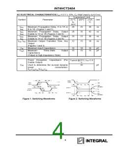
AC ELECTRICAL CHARACTERISTICS(VCC=5.0 V ± 10%, CL=50pF,Input tr=tf=6.0 ns)
Guaranteed Limit
Symbol
Parameter
Unit
25 °C ≤85°C ≤125
to
-55°C
20
°C
30
42
38
18
tPLH
tPHL
tPLZ
tPHZ
tPZH
tPZL
,
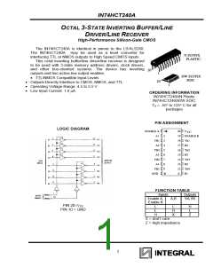
Maximum Propagation Delay, A to YA or
B to YB (Figures 1 and 3)
Maximum Propagation Delay, Output
Enable to YA or YB (Figures 2 and 4)
Maximum Propagation Delay, Output
Enable to YA or YB (Figures 2 and 4)
25
35
31
15
ns
ns
ns
ns
,
28
25
12
,
tTLH, tTHL Maximum Output Transition Time, Any
Output
(Figures 1 and 3)
CIN
COUT
Maximum Input Capacitance
10
15
10
15
10
15
pF
pF
Maximum
Three-State
Output
Capacitance
(Output in High-Impedance State)
Power Dissipation Capacitance (Per
Enable Output)
Typical @25°C,VCC=5.0
V
CPD
Used to determine the no-load dynamic
55
pF
power
consumption:
PD=CPDVCC2f+ICCVCC
Figure 1. Switching Waveforms
Figure 2. Switching Waveforms
4

 INTEGRAL [ INTEGRAL CORP. ]