TLE 4726
Application Hints
The TLE 4726 is intended to drive both phases of a stepper motor. Special care has
been taken to provide high efficiency, robustness and to minimize external components.
Power Supply
The TLE 4726 will work with supply voltages ranging from 5 V to 50 V at pin VS. As the
circuit operates with chopper regulation of the current, interference generation problems
can arise in some applications. Therefore the power supply should be decoupled by a
0.22 µF ceramic capacitor located near the package. Unstabilized supplies may even
afford higher capacities.
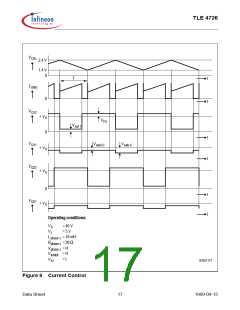
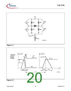
Current Sensing
The current in the windings of the stepper motor is sensed by the voltage drop across R1
and R2. Depending on the selected current internal comparators will turn off the sink
transistor as soon as the voltage drop reaches certain thresholds (typical 0 V, 0.25 V,
0.5 V and 0.75 V); (R1 , R2 = 1 Ω). These thresholds are neither affected by variations
of VL nor by variations of VS .
Due to chopper control fast current rises (up to 10 A/µs) will occur at the sensing
resistors R1 and R2 . To prevent malfunction of the current sensing mechanism R1 and
R2 should be pure ohmic. The resistors should be wired to GND as directly as possible.
Capacitive loads such as long cables (with high wire to wire capacity) to the motor should
be avoided for the same reason.
Synchronizing Several Choppers
In some applications synchrone chopping of several stepper motor drivers may be
desireable to reduce acoustic interference. This can be done by forcing the oscillator of
the TLE 4726 by a pulse generator overdriving the oscillator loading currents
(approximately ± 100 µA). In these applications low level should be between 0 V and 1 V
while high level should be between 2.6 V and VL .
Optimizing Noise Immunity
Unused inputs should always be wired to proper voltage levels in order to obtain highest
possible noise immunity.
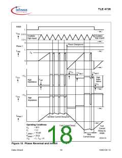
To prevent crossconduction of the output stages the TLE 4726 uses a special break
before make timing of the power transistors. This timing circuit can be triggered by short
glitches (some hundred nanoseconds) at the Phase inputs causing the output stage to
become high resistive during some microseconds. This will lead to a fast current decay
during that time. To achieve maximum current accuracy such glitches at the Phase
inputs should be avoided by proper control signals.
Data Sheet
21
1999-09-15

 INFINEON [ Infineon ]