TDA5235
Functional Description
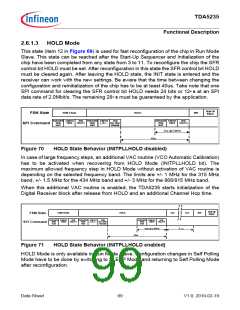
2.6.1.3 HOLD Mode
This state (item 12 in Figure 69) is used for fast reconfiguration of the chip in Run Mode
Slave. This state can be reached after the Start-Up Sequencer and Initialization of the
chip have been completed from any state from 3 to 11. To reconfigure the chip the SFR
control bit HOLD must be set. After reconfiguration in this state the SFR control bit HOLD
must be cleared again. After leaving the HOLD state, the INIT state is entered and the
receiver can work with the new settings. Be aware that the time between changing the
configuration and reinitialization of the chip has to be at least 40us. Take note that one
SPI command for clearing the SFR control bit HOLD needs 24 bits or 12μs at an SPI
data rate of 2.0Mbit/s. The remaining 28μs must be guaranteed by the application.
Wait till
SSync
EOM-Check
HOLD
INIT
FSM State
Instruction Address
Data
Instruction Address
Data
Instruction Address
Data
Write
0x02
CMC0
HOLD=1
Write
0x02
x_PLL... (sel. other
Write
0x02
CMC0
HOLD=0
SPI Command
channel)
12us @ 2.0MHz
40us
Figure 70
HOLD State Behavior (INITPLLHOLD disabled)
In case of large frequency steps, an additional VAC routine (VCO Automatic Calibration)
has to be activated when recovering from HOLD Mode (INITPLLHOLD bit). The
maximum allowed frequency step in HOLD Mode without activation of VAC routine is
depending on the selected frequency band. The limits are +/- 1 MHz for the 315 MHz
band, +/- 1.5 MHz for the 434 MHz band and +/- 3 MHz for the 868/915 MHz band.
When this additional VAC routine is enabled, the TDA5235 starts initialization of the
Digital Receiver block after release from HOLD and an additional Channel Hop time.
Wait till
SSync
EOM-Check
HOLD
VAC
VAC
INIT
FSM State
Instruction Address
Data
Instruction Address
Data
Instruction Address
Data
Write
0x02
CMC0
HOLD=1
Write
0x02
x_PLL... (sel. other
channel)
Write
0x02
CMC0
HOLD=0
SPI Command
tC_Hop
12us @ 2. 0MHz
40us
Figure 71
HOLD State Behavior (INITPLLHOLD enabled)
HOLD Mode is only available in Run Mode Slave. Configuration changes in Self Polling
Mode have to be done by switching to SLEEP Mode and returning to Self Polling Mode
after reconfiguration.
Data Sheet
99
V1.0, 2010-02-19

 INFINEON [ Infineon ]