TC1767
Electrical Parameters
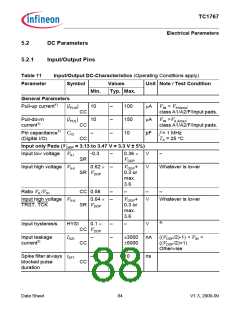
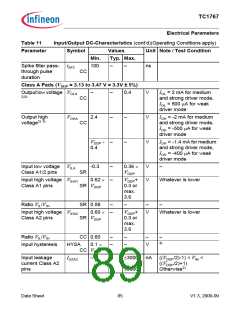
Table 11
Input/Output DC-Characteristics (cont’d)(Operating Conditions apply)
Parameter
Symbol
Values
Unit Note / Test Condition
Min.
Typ. Max.
Spike filter pass- tSF2
through pulse
100
–
–
ns
CC
duration
Class A Pads (VDDP = 3.13 to 3.47 V = 3.3V ± 5%)
Outputlowvoltage VOLA
–
–
0.4
V
V
V
IOL = 2 mA for medium
and strong driver mode,
IOL = 500 µA for weak
driver mode
2)3)
CC
Output high
voltage2) 3)
VOHA
2.4
–
–
I
OH = -2 mA for medium
and strong driver mode,
OH = -500 µA for weak
driver mode
OH = -1.4 mA for medium
and strong driver mode,
OH = -400 µA for weak
CC
I
V
0.4
DDP - –
–
I
I
driver mode
Input low voltage VILA
Class A1/2 pins
-0.3
–
0.36 ×
VDDP
V
V
–
SR
Input high voltage VIHA1
0.62 × –
VDDP+
Whatever is lower
Class A1 pins
SR VDDP
0.3 or
max.
3.6
Ratio VIL/VIH
SR 0.58
–
–
–
–
Input high voltage VIHA2
Class A2 pins
0.60 × –
SR VDDP
VDDP
+
V
Whatever is lower
0.3 or
max.
3.6
Ratio VIL/VIH
CC 0.60
–
–
–
–
–
–
4)
Input hysteresis
HYSA
0.1 ×
V
CC VDDP
Input leakage
current Class A2
pins
IOZA2
–
–
±3000 nA ((VDDP/2)-1) < VIN <
((VDDP/2)+1)
±6000
Otherwise2)
Data Sheet
85
V1.3, 2009-09

 INFINEON [ Infineon ]