ICE3BR1765JZ
Electrical Characteristics
4
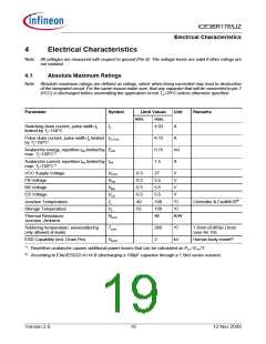
Electrical Characteristics
Note: All voltages are measured with respect to ground (Pin 8). The voltage levels are valid if other ratings are
not violated.
4.1
Absolute Maximum Ratings
Note: Absolute maximum ratings are defined as ratings, which when being exceeded may lead to destruction
of the integrated circuit. For the same reason make sure, that any capacitor that will be connected to pin 7
(VCC) is discharged before assembling the application circuit.Ta=25°C unless otherwise specified.
Parameter
Symbol
Limit Values
Unit
Remarks
min.
max.
Switching drain current, pulse width tp
limited by Tj=150°C
Is
-
-
-
-
4.03
A
Pulse drain current, pulse width tp limited ID_Puls
by Tj=150°C
6.12
0.15
1.5
A
Avalanche energy, repetitive tAR limited by EAR
mJ
A
max. Tj=150°C1)
Avalanche current, repetitive tAR limited by IAR
max. Tj=150°C1)
VCC Supply Voltage
FB Voltage
VVCC
VFB
VBA
VCS
Tj
-0.3
-0.3
-0.3
-0.3
-40
-55
-
27
V
5.5
5.5
5.5
150
150
96
V
BA Voltage
V
CS Voltage
V
Junction Temperature
Storage Temperature
°C
°C
K/W
Controller & CoolMOS®
TS
Thermal Resistance
Junction -Ambient
RthJA
Soldering temperature, wavesoldering
only allowed at leads
Tsold
-
-
260
2
°C
1.6mm (0.063in.) from
case for 10s
Human body model2)
ESD Capability (incl. Drain Pin)
VESD
kV
1)
Repetitive avalanche causes additional power losses that can be calculated as PAV=EAR*f
According to EIA/JESD22-A114-B (discharging a 100pF capacitor through a 1.5kΩ series resistor)
2)
Version 2.0
19
12 Nov 2009

 INFINEON [ Infineon ]