CoolSET™-F3
Pin Configuration and Functionality
1
Pin Configuration and Functionality
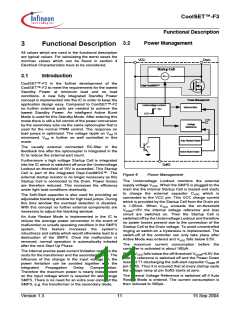
1.1
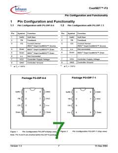
Pin Configuration with PG-DIP-8-6
1.2
Pin Configuration with PG-DIP-7-1
Pin
Symbol Function
Pin
Symbol Function
1
2
3
SoftS
FB
Soft-Start
Feedback
1
2
3
SoftS
FB
Soft-Start
Feedback
CS
Current Sense/
CS
Current Sense/
650V1) Depl-CoolMOS™ Source
650V1) Depl-CoolMOS™ Source
650V1) Depl-CoolMOS™ Drain
650V1) Depl-CoolMOS™ Drain
4
5
Drain
Drain
4
5
n.c.
Not connected
650V1) Depl-CoolMOS™ Drain
Drain
-
7
-
-
6
7
n.c.
VCC
GND
Not Connected
VCC
GND
Controller Supply Voltage
Controller Ground
Controller Supply Voltage
Controller Ground
8
8
1)
1)
at Tj = 110°C
at Tj = 110°C
Package PG-DIP-7-1
Package PG-DIP-8-6
SoftS
FB
1
8
7
6
5
GND
VCC
n.c.
SoftS
FB
1
8
7
GND
VCC
2
2
CS
3
4
CS
3
4
Drain
Drain
n.c.
5
Drain
Figure 2
Pin Configuration PG-DIP-7-1(top view)
Figure 1
Pin Configuration PG-DIP-8-6(top view)
Note: Pin 4 and 5 are shorted within the DIP 8 package.
Version 1.3
7
15 Sep 2004

 INFINEON [ Infineon ]