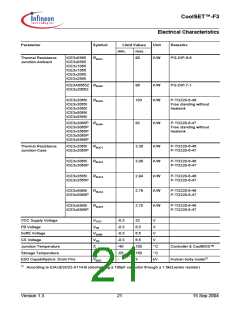
CoolSET™-F3
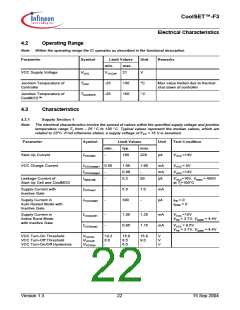
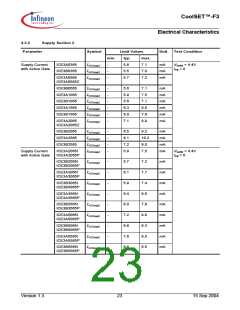
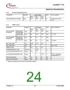
Electrical Characteristics
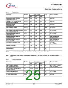
4.3.5
Control Unit
Parameter
Symbol
Limit Values
Unit
Test Condition
min.
typ.
max.
Deactivation Level for SoftS
Comparator C7 by C2
VSoftSC2
3.85
4.00
4.15
4.57
5.60
-
V
VFB > 5V
Clamped VSoftS Voltage during
Normal Operating Mode
VSoftSclmp 4.23
4.40
5.40
1.3
V
VFB = 4V
Activation Limit of
Comparator C3
VSoftSC3
ISoftSstart
5.20
-
V
VFB > 5V
SoftS Startup Current
mA
V
VSoftS = 0V
VSoftS > 5.6V
VSoftS > 5.6V
Over Load & Open Loop Detection VFBC4
Limit for Comparator C4
4.62
1.23
3.85
3.25
16.1
130
-
4.80
1.30
4.00
3.40
17.1
140
8.0
4.98
1.37
4.15
3.55
18.1
150
-
Active Burst Mode Level for
Comparator C5
VFBC5
VFBC6a
VFBC6b
VVCCOVP
TjSD
V
Active Burst Mode Level for
Comparator C6a
V
After Active Burst
Mode is entered
Active Burst Mode Level for
Comparator C6b
V
After Active Burst
Mode is entered
Overvoltage Detection Limit
Thermal Shutdown1)
Spike Blanking
1)
V
VFB > 5V
VSoftS < 4.0V
°C
µs
tSpike
The parameter is not subject to production test - verified by design/characterization
Note: The trend of all the voltage levels in the Control Unit is the same regarding the deviation except VVCCOVP
and VVCCPD
4.3.6
Current Limiting
Parameter
Symbol
Limit Values
Unit
Test Condition
min.
typ.
max.
Peak Current Limitation
(incl. Propagation Delay)
Vcsth
VCS2
tLEB
0.97
1.02
1.07
V
dVsense / dt = 0.6V/µs
(see Figure 15)
Peak Current Limitation during
Active Burst Mode
0.232
-
0.257
220
0.282
V
Leading Edge Blanking
-
ns
µA
VSoftS = 4.4V
VCS =0V
CS Input Bias Current
ICSbias
-1.0
-0.2
0
Version 1.3
25
15 Sep 2004

 INFINEON [ Infineon ]