AIROC™ Bluetooth® system on chip for automotive applications
Specifications
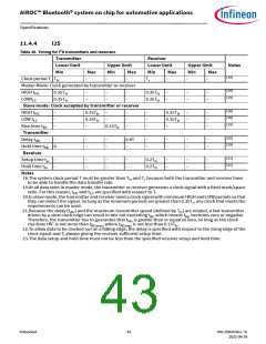
11.4.4
I2S
Table 30. Timing for I2S transmitters and receivers
Transmitter
Receiver
Lower limit
Min
Clock period T Ttr
Upper limit
Min Max
Lower limit
Upper limit
Min Max
Notes
Max
–
Min
Tr
Max
–
[18]
–
–
–
–
Master Mode: Clock generated by transmitter or receiver
[19]
[19]
HIGH tHC
LOWtLC
0.35Ttr
0.35Ttr
–
–
–
–
–
–
0.35Ttr
0.35Ttr
–
–
–
–
–
–
Slave mode: Clock accepted by transmitter or receiver
[18]
[18]
[19]
HIGH tHC
LOW tLC
–
–
–
0.35Ttr
0.35Ttr
–
–
–
–
–
–
–
–
–
0.35Ttr
0.35Ttr
–
–
–
–
–
–
Rise time tRC
Transmitter
Delay tdtr
Hold time thtr
Receiver
0.15Ttr
[20]
[19]
–
0
–
–
–
–
0.8T
–
–
–
–
–
–
–
–
–
[21]
[21]
Setup time tsr
Hold time thr
Notes
–
–
–
–
–
–
–
–
0.2Ttr
0.2Ttr
–
–
–
–
–
–
18.The system clock period T must be greater than Ttr and Tr because both the transmitter and receiver have
to be able to handle the data transfer rate.
19.At all data rates in master mode, the transmitter or receiver generates a clock signal with a fixed mark/space
ratio. For this reason, tHC and tLC are specified with respect to T.
20.In slave mode, the transmitter and receiver need a clock signal with minimum HIGH and LOW periods so that
they can detect the signal. So long as the minimum periods are greater than 0.35Tr, any clock that meets the
requirements can be used.
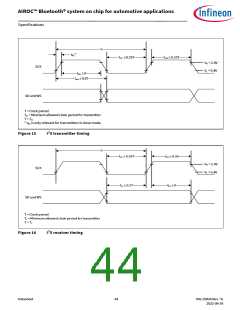
21.Because the delay (tdtr) and the maximum transmitter speed (defined by Ttr) are related, a fast transmitter
driven by a slow clock edge can result in tdtr not exceeding tRC which means thtr becomes zero or negative.
Therefore, the transmitter has to guarantee that thtr is greater than or equal to zero, so long as the clock
rise-time tRC is not more than tRCmax, where tRCmax is not less than 0.15Ttr.
22.To allow data to be clocked out on a falling edge, the delay is specified with respect to the rising edge of the
clock signal and T, always giving the receiver sufficient setup time.
23.The data setup and hold time must not be less than the specified receiver setup and hold time.
Datasheet
43
002-25826 Rev. *G
2022-09-24

 INFINEON [ Infineon ]